Airborne radars

Contents
- 1 Overview
- 2 Airborne radar controls
- 3 Airborne radars user interface
- 4 Radar operation
- 5 Radar scan patterns
- 6 Types of airborne radars
- 7 Factors affecting radar performance
- 8 Airborne radars tips and ticks
- 9 Aircraft equipped with radars
- 10 Media
- 11 See also
- 12 External links
Overview
Airborne Radars were added to the game in Update 1.87 "Locked On". Airborne radars are found on aircraft at both low and high ranks, if an aircraft is equipped with radar then a radar display will be present in the right portion of a player's screen, as well as a compass displaying the player's current heading and the directions to detected targets at the top of the screen.
There are two main types of airborne radar in the game, target detection (search) radars and target tracking radars. Target detection radars will detect aircraft (both friendly and hostile) and display them as a "blip" on the radar display, it will also place a triangle on the compass showing what direction the detected aircraft is in. Target tracking radars are more advanced; they allow the player to "lock-on" to a target. Once a target has been locked on to, a box will appear around it on the HUD and a read-out will provide the distance to the target and the closing speed between the player's aircraft and the target. Depending on the aircraft being flown tracking radars may also be able to provide an accurate firing lead indicator, once the player closes to within approximately 0.7 km.
Airborne radar controls
| For information about IRST see the corresponding article. |
| Airborne Radar Controls | ||
|---|---|---|
| Control name | Default Keybind (PC keyboard & mouse) |
Description |
| Switch Radar/IRST search on/off | Alt+R | Turns the vehicle's search radar on or off |
| Switch between Radar and IRST | ||
| Change Radar/IRST mode | Unbound | Switches the radar between search mode and tracking mode for multi-mode radars, or normal and pulse-doppler mode for applicable radars |
| Radar/IRST beyond/within visual range combat | ||
| Change Radar/IRST search mode | Unbound | Toggles between the radar's search modes e.g. narrow scan or wide scan |
| Change Radar/IRST scope scale | Unbound | Changes the range scale of the radar display |
| Select Radar/IRST target to lock | Alt+T | Selects which target on the display to lock on to |
| Lock Radar/IRST on target | Alt+F | Locks onto the selected or nearest target on radar display or turns tracking radar on |
Airborne radars user interface
Basic user interface

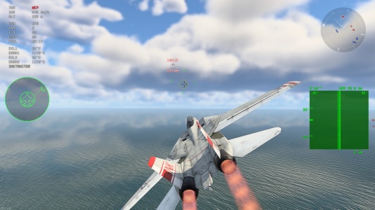
As previously mentioned, aircraft equipped with radars can be identified by the presence of the radar display and compass on the HUD (see image to the right).
Below the linear compass at top centre is a small arrow which displays the aircraft's current heading. Targets detected by the radar will also have their bearing displayed on the compass as a triangle.
One or two radar scopes will be present in the right hand portion of the screen; they are discussed in detail later in the article. If the radar is experiencing surface clutter interference then an icon (visible in the image to the right) will be present next to the power indicator, consisting of two arrows and a series of bars. The number of bars illuminated indicates how severe surface clutter is (one bar means minor interference, four bars means major interference); if the aircraft has two radars activated then each one will have its own surface clutter indicator.
If the radar has been deactivated, a separate icon will be displayed instead of the radar display.
There are several different types of radar target which can appear on the radar display and compass. A basic radar target will appear as a bar on the radar display and a triangle on the compass. The radar target which is selected will appear with a vertical line either side of it; and the radar target which is locked on to will appear with a box around it. Some radars are fitted with Identification Friend or Foe (IFF) systems, these radars will display friendly radar targets with a horizontal line above them.

Radar display types
Plan Position Indicator (PPI)

The default display is a "Plan Position Indicator" (PPI) type display. It is in the shape of a sector and represents a top-down view of the area in front of the aircraft. The radar is located in the bottom centre of the display; the distance a target is from the centre point shows how far away it is, while its angle from the centre line shows its azimuth.
| The PPI can display the range and azimuth of a target, but not its elevation |
When the radar is turned on, a bar representing the current scan angle sweeps back and forth, radially, about the centre point. A series of four concentric range rings can be used to determine how far away the detected targets are (to get the distance between rings divide the range scale by 4), and a series of bars (at 15-degree angles) help tell the azimuth of detected targets. If a radar has an azimuth scan angle of less than 180 degrees then the display is still a semicircle.
The readout to the left of the scope shows the azimuth and elevation scan angles, while the readout to the right shows the currently selected range scale.
In the image to the right there are three targets, all approximately 4.5 km away from the player. One target is at an azimuth of 0° (directly in front of the player) while one is at an azimuth of approximately -30° (30° to the left of the player), and one is at an azimuth of approximately +30° (30° to the right of the player). It is not possible to tell the target's elevation difference from the player using only the PPI.
C-scope

In addition to the PPI some aircraft have access to a C-scope type display (positioned underneath the PPI). The C-scope displays the same radar targets as the PPI, but in a different format. Whereas a PPI is a top-down view, the C-scope is forwards-looking. It is a rectangular display where how far from the azimuth centre line a target is shows its azimuth and how far from the elevation centre line a target is shows its elevation.
| The C-scope can display the azimuth and elevation of a target, but not its range |
In addition to the azimuth and elevation centre lines there are two other horizontal lines on the display, these show the minimum and maximum elevation scan angles of the radar. It should be noted that the degree values shown to the right of the C-scope are the minimum and maximum elevation angles of the scope, not the radar.
In the image to the right there are three targets, all slightly below the player (they are below the elevation centre line). One target is at an azimuth of 0° (directly in front of the player) while one is at an azimuth of approximately -30° (30° to the left of the player), and one is at an azimuth of approximately +30° (30° to the right of the player). It is not possible to tell the target's range from the player using only the PPI.
By using a combination of the PPI and C-scope you can work out the range, azimuth and elevation of individual targets.
B-Scope

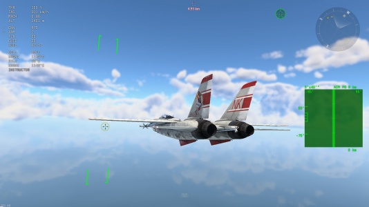
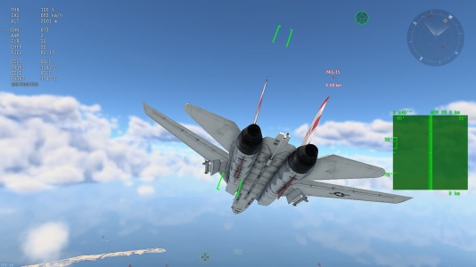
An alternative radar display (instead of the PPI) is available in the form of a "B-Scope" type display. It can be enabled via the "Use rectangular radar indicator" setting. It is a square display providing a 2-D "top-down" representation of space, the vertical axis represents the range to the target and the horizontal axis represents the azimuth (angle) of the target. The maximum and minimum azimuth scan angles are displayed in the top corners of the display, as is the range setting. A series of four range bars can be used to determine how far away detected targets are, and vertical bars can be used to determine what direction the target is in. When the radar is turned on a vertical bar representing the current scan angle moves horizontally, back and forth, across the display.
Radar operation
Basic radar operation

When turned on, radars will scan a pyramid or cone-shaped area in front of the player's aircraft (illustrated in the image to the right). Radars can only detect targets which fall within their scanning area, the size and shape of which varies depending on the model of radar. Each radar has a maximum and minimum azimuth scan angle (how far to each side it will scan); and a maximum and minimum elevation scan angle (how far up and down it will scan). Radars also have a minimum detection range (typically 150 - 300 m), below which targets will not be detected (not that you should need a radar to see an aircraft that close).
As with other characteristics, the maximum detection range varies greatly between radars (from as little as 4 km, to in excess of 40 km). Targets are not guaranteed to be detected at the radar's maximum detection range. The range at which a target is detected will depend on how much radar energy it reflects back to the radar, which is in turn determined by its Radar Cross-Section (RCS). Generally larger aircraft have a larger RCS so will be detected at greater ranges; for example the AI Mk. X radar (fitted to the Sea Venom FAW 20) can detect the large G5N1 bomber at its maximum detection range of 14 km, however, can only detect the much smaller He 162 A-1 at approximately 9 - 9.5 km.
When a radar detects a target, it appears as a "blip" on the radar display. Its position will not be updated until the radar detects it again (usually on the next scan, as indicated by the sweeping bar). When the target is re-detected, its old blip is removed and a new one plotted at the location it was re-detected at. If enough time elapses without a target being re-detected (either due to the target now being outside of the radar's scanning area, or simply the radar not scanning fast enough) then the target's blip will fade and disappear from the radar display. Likewise after a period of not being detected a target which has been locked onto will be lost.
Radar modes
SRC
The Search (SRC) mode is the basic search radar mode. It is prone to ground clutter, or clouds cluttering it. This means if behind the enemy is something that reflects radar waves, the enemy will be hidden from your radar. So if you are looking downwards its not recommended to use this mode, but if you are looking upwards and there are no clouds in view you should can use this mode if no better is available.
SRC PD
The Pulse-Doppler (PD) mode uses a signal processing filter, which eliminates out returns that have closure rate of your planes speed. So the ground will be filtered out, but also objects moving perpendicular towards your plane (so called notching). It also may have different blind spots resulting from the frequencies used in the radar, so that when chasing a target you might fail to get a lock on. Use fast IR missiles like the R-27ET then.
SRC PD HDN
It works like SRC PDN but is made for head-on engagements. Some radars will completely filter out targets that dont move towards you in this mode.
SRC PDV HDN
The display shows the targets not sorted by distance but by velocity. This makes it easier to select the target coming towards you at the fastest speed.
SRC MTI
MTI stands for moving target indication. It allows look-down capability, which means it filters out ground clutter. It is harder to notch than SRC PD but has a smaller range. Also even when the radar is able to maintain lock the missiles seeker might be not able to follow the target in a notching situation.
SRC IR
Not actually a radar but optical tracking. See IRST.
TWS
See below for Track-while-scan mode.
TWS HDN
Works like TWS mode but shows only targets that fly towards you.
Radar range scale
Some radars allow for the range scale of the radar scope to be changed, in order to change the range scale a key needs to be bound to the "Change radar scope scale" control. The currently selected range scale is shown on the radar display, if the range scale is changed then the display will stay the same size, but the targets will be placed on the display according to the new scale. It is worth noting that the default range scale may be less than the radar's maximum detection range, so you may need to increase the range scale in order to make full use of your radar. Some radars can be set to a range scale far in excess of the radar's maximum detection range; targets will not be detected outside of a radar's maximum detection range, regardless of range scale setting.
Radar search mode
Some radars allow for different search modes to be activated. The default search mode on radars usually (although not always) makes use of the radar's full scanning area. While this is useful for detecting targets in a wide area this can come with the drawback of each scan taking longer to complete (as the radar has to scan a larger area), meaning that targets are updated less frequently on the radar display. Some radars allow the operator to change the search mode so that the radar only scans a smaller area, this means that targets can be updated on the radar more often, but has the drawback of targets only being detectable in a more narrow area in front of the player's aircraft. This ability is primarily useful for keeping track of fast moving or manoeuvring targets, where the slower scan time associated with a full scan, would make tracking the movement of such a target difficult. When the radar mode is changed the PPI will remain the same size / shape, but two hard lines will appear indicating the new scanning limits; rang rings and azimuth bars will not be drawn outside of the lines. In order to change radar scanning mode, a key needs to be bound to the "Change radar search mode" control (located under the "Weaponry" heading of the aircraft controls menu).
| The modes available vary depending on the specific radar. Some radars change the azimuth scanning angles, while others change the elevation scanning angles. |
Detecting/tracking ground targets
Some search radars and tracking radars are capable of detecting and locking on to ground targets. For these radars ground targets appear on the PPI the same as air targets, and can be locked on to the same way. This functionality is not massively useful, but can come in handy when trying to find player controlled tanks to kill. Ground clutter also limits how effective these radars are at finding ground targets. See individual radar pages to find out if they can detect ground targets.
Air Combat Maneuvering (ACM)
Some radars feature a so called Air Combat Maneuvering Mode which will scan for a target in a narrow cone and a reduced range. If a target is found, the radar will switch automatically to Tracking Mode and lock on the target which was just found. The radar on the F-14A features three ACM modes which have different search rectangles for different situations.
ACM mode with a centered small rectangle search area.
ACM mode with avertical centered search area.
ACM mode with a vertical upwards looking search area.


ACM HMD
Some planes have a so called head mounted display (HMD), which allows the pilot to select targets by looking into their direction. Switch the radar into ACM HMD mode and use your look around button to align the square with the target you want to lock on. Then push "select target" to confirm and the radar tries to lock.
Radar scan patterns
| This topic is included for those who want a better understanding of how different radars scan for targets, it is not essential knowledge, but may be useful. |
Raster Scan

Most search radars in the game use what is known as a bi-directional raster scan (see image to the right). The radar beam starts in the top corner of the scanning area and moves horizontally until it reaches the other side of the scanning area; it then drops down and moves horizontally in the other direction until it reaches the original side of the scanning area. The process repeats until the radar beam has reached the bottom corner of the scanning area. At this point the beam will do one of two things; if the radar uses a one-way raster scan then the beam will move directly upwards from its finishing position until it reaches the top corner of the scanning area, where it starts the process again. If it is a two-way raster scan then when the beam reaches the bottom corner its movement will reverse and it will work its way back up to the top of the scanning area, following the path it just took in reverse.
The raster scan pattern allows the radar to identify targets on different elevations. Each sweep the radar makes on a different elevation is known as a bar; for example the scan pattern shown in the image to the right has 4 bars as the radar completes 4 scans in the process of covering the scan area. The number of bars in the scan, and the height of each bar (measured in degrees) width of the scan in the elevation axis; the width of the scan in the azimuth axis is determined by how far to each side the radar scans.
| The PPI shows the radar sweeping over each bar, so on a 4 bar scan a target on the PPI may only be refreshed once every 4 sweeps (due to the radar sweeping over a bar the target is not located in). |
If you know the number of bars in the radar's scan pattern, the height of each bar, and the vertical offset (more on this later) then you can calculate the minimum and maximum elevation scanning angles of the radar (how far up and down the radar see). You start by calculating the elevation width of the radar as follows:
elevation width = number of bars * height of each bar
At this point it is tempting to just divide the elevation width by 2 and conclude that the resulting number is how far off the elevation centre line in each direction the radar can see (e.g. for a elevation width of 30° the radar can see 15° up and 15° down), however this is not always the case. Some radars have more bars above the elevation centre line than below it (or vice versa), that is to say they can look further up than they can down or vice versa. This gives rise to the concept of a "vertical offset" (measured in degrees), i.e. how far upwards (or downwards) the bars are shifted from being evenly distributed either side of the elevation centre line.
When this is factored in we get the following equations for working out the minimum and maximum elevation limits of the radar:
maximum elevation angle = (elevation width / 2) + vertical offset
minimum elevation angle = (-1 * (elevation width / 2)) + vertical offset
For example if we take the AN/APS-21 radar. Its scan pattern uses 15 bars, each 2° in height, giving us an elevation width of 30°; with a vertical offset of +5°. If we put this into the equations above we get the following:
maximum elevation angle = (30 / 2) + 5 = 20°
minimum elevation angle = (-1 *(30 / 2)) + 5 = -10°
This means the AN/APS-21 radar can detect targets up to 20° above the player and 10° below the player.
Conical Scan

Tracking radars in the game use what is known as a conical scan, instead of a raster scan. In a conical scan the radar beam rotates around a central axis, with a few degrees offset from the centre. The result of this is that the radar scans a narrow cone shaped area in front of the aircraft. The rotation of the beam also means the radar to tell where the target is within the cone, allowing the radar to effectively track the target.
Continuously updating radars

The German Lichtenstein family of radars (the radars found on German WW2 planes) are unique compared to other radars currently in the game, in that they do not scan for targets. Instead, they constantly emit a cone of radar energy and detect the return. This gives them the advantage of having the radar constantly updating (instead of updating only when the radar scans over a target). However, as a trade-off, these radars have a poor range (only 4 or 5 km) and a narrow scanning area. When these radars are active, instead of seeing a sweeping line the entire scanning area of the radar is illuminated and radar blips update continuously. An example of this can be seen in the image to the right.
Types of airborne radars
The two main types of radar are target detection radars and target tracking radars. Target detection radars are found on vehicles from rank 1, however, the more advanced target tracking radars are reserved for high-rank vehicles. Vehicles are typically equipped with target tracking radars in addition to target detection radars, with the two working in tandem.
Target detection radars
Target detection radars, also known as search radars, have no tracking ability and simply display detected targets on the radar display and compass. The basic operation of target detection radars has been discussed previously in this article. Target detection radars are available from rank 1, radars found at higher ranks have much better characteristics (larger scanning area, better range, etc.).
Target tracking radars
Target tracking radars are fitted to some aircraft in addition to target detection radars. They typically have a short range compared to the aircraft's search radar (hence a search radar is equipped to find targets at long ranges), however, they have the ability to track and "lock-on" to targets. Tracking radars typically have different scanning areas than the search radar equipped to the aircraft; when an aircraft is equipped with a tracking radar, its tracking area is shown as a darker area within the radar display (as seen in the image to the right).
A target can only be locked onto if it is within the tracking radars maximum range and search area (the dark section of the radar display). Once a target is locked on to, a box will appear around it, as well as around its icon on the radar display and compass (to differentiate the locked target from other radar targets). An accurate distance to the target will be displayed next to the locked target on the HUD, as well as an accurate closing speed (speed will read negative if the target is moving away from you). If your aircraft supports a lead indicator, then an accurate firing lead indicator will appear once you close to within 500-700 m of the target.
In order to maintain a lock on the target, you need to keep it within the tracking radars maximum range and tracking area; if the target is not detected by the tracking radar in too long the lock will be lost.
Obtaining and maintaining a radar lock

There are two ways to lock on to a target when using a tracking radar. When a search radar has detected targets which are within the tracking radar's tracking area one of them will be selected (have a vertical line either side of it). You can change the selected target by pressing the "Select radar target to lock on" key, when the "Lock radar target on" key is pressed it will turn on the tracking radar and automatically attempt to lock on to the selected target. Alternatively you can press the "Lock radar target on" or "Change radar mode" key (depending on radar type) to turn on (or switch to) the tracking radar. When this happens the tracking radar will begin a conical scan pointing directly forwards; a flashing green square will appear on the screen (image to the right). If you place the box over an aircraft then the tracking radar will try to lock on to it; note that surface clutter and other factors may inhibit the radar from locking on. The target you want to lock on to using this method should be within the range limits listed to the right of the box.
Like with real radars, multiple targets in close proximity to each other can confuse the tracker. If a target is locked and another aircraft flies past it, it is possible for the tracker to lose the lock on the target, or even transition the lock onto the other aircraft (something which also happens to real radar systems). In the previously described scenarios (or depending on how the target is moving relative to the player's aircraft), it is also possible for the target lead indicator to become temporarily inaccurate.
In order for a radar lock to be maintained, the target needs to be kept within the tracking radar's tracking area. If the target leaves this area for more than a short period of time, the lock will be lost. Try to use the whole width of the possible tracking area, which often is beyond the pilots field of view, so you don't have to fly directly towards your target (also see "crank maneouvre").
Multi-mode radars
Some radars such as the AN/APQ-100 (found on the F-4 Phantom II) are what are known as multi-mode radars, the same radar antenna functions as both a search and tracking radar, although not at the same time. These radars can be toggled between search and tracking mode by pressing the "Change radar mode" key. Overall they function pretty much the same as aircraft with independent search and tracking radars, however as the antenna is being used for both searching and tracking it cannot do both at the same time. If you are tracking a target then you will lose search functionality.
Note: The RP-5 does not count as a multi-mode radar as although it is responsible for both searching and tracking it does so using two separate antennas.
Track While Scan (TWS)
Some modern radars such as the AN/AWG-9 (found on the F-14A Early) and PS-46/A (fitted to the JA37C) feature a "Track While Scan" (TWS) mode, in which targets can be tracked while the radar simultaneously scans for other targets. One big advantage of such a radar is that tracking while in TWS mode doesn't trigger a spike in the enemies' radar warning receivers, because the radar intensity is lower. It can track multiple targets at the same time, making it a very powerful tool in conjunction with other systems such as active radar-homing and radar-slavable missiles. However, a hard lock is still required to be able to use semi-active radar-homing missiles.
Radar gunsights

Radar gunsights are fitted to a number of aircraft in the game. If there is no real radar, these aircraft can be identified by the presence of the radar gunsight indicator (see image to the right). A radar gunsight is very similar to a regular gyroscopic gunsight, however whereas on a regular gunsight the pilot would have to manually dial in a range, radar gunsights use a small ranging radar to automatically input the range for the target the pilot is pointing his guns at.
In game radar gunsights will automatically adjust the aircraft's gyroscopic gunsight in the cockpit view, making it more accurate. Modern planes also get a radar gunsight in 3rd person view for the locked target if you come close enough.
You can turn the radar gunsight on and off by pressing the "Lock radar target on" key. Often there is only a short range in which it will work like 200 - 500m distance.

|
Radar gunsight tutorial by TeaRex
|
Factors affecting radar performance
There are a number of factors which affect the performance of airborne radars. The details of different radars can be found on their individual pages, this section explains what the performance characteristics mean and what their significance is.
Search radars
Maximum detection range
The maximum range of the radar is the maximum theoretically possible distance at which a search radar can detect a target. It is unlikely however that aircraft will be detected until they are much closer than this range. The range at which a target will actually be detected depends on its radar cross section (in basic terms how big it is), and other factors such as surface clutter.
Base detection range
This is the range at which a target can be detected regardless of how small its radar cross section is before taking into account surface clutter and other factors. If the radar is not being affected by surface clutter or you are playing arcade battles (where surface clutter is not modelled) then this is effectively the range at which you are guaranteed to detect a target aircraft, no matter how small it is; larger aircraft may be detected further away than this range.
| In Realistic and Simulator Battles where surface clutter is modelled, targets may not be detected until they are much closer than this range |
Minimum detection range
Radars have a minimum range, at which they can function, targets closer than the minimum range cannot be detected by the radar.
Azimuth scan limits
The azimuth scan limits are how far to each side the radar can scan. For example, scan angles of ±75° means that the radar can see targets up to 75° to the left and 75° to the right.
Elevation scan limits
The elevation scan limits are how far to up and down in total, the radar might take multiple scans to cover its entire elevation range, see the raster scan section for more information.
Period
The period of the radar is how long it takes to complete one scan of its entire scanning area. This will take multiple individual sweeps, if the scan pattern has more than one raster bar.
Tracking radars
Maximum tracking range
The maximum tracking range is the maximum range at which a radar can maintain a track on a target.
Minimum tracking range
Tracking radars have a minimum range, below which they are unable to track targets. You cannot initiate tracks on targets closer than the minimum range, and if a tracked target comes closer than the minimum range the track will be lost.
Azimuth tracking limits
The azimuth tracking limits determine how far to each side the radar can track targets.
Elevation tracking limits
The elevation tracking limits determine how far up and down the radar can track targets.
Clutter
| Surface clutter is not present in Arcade Battles. |
Radars operate by emitting radio waves which then reflect off of targets and return to the radar. Unfortunately the radio waves also reflect off the ground, and other objects, leading to unwanted returns known as clutter. The type of clutter modelled in War Thunder is surface clutter (radar returns from the ground or sea).
In-game surface clutter is modelled as a green haze covering areas of the PPI, the more severe the ground clutter the more intense the haze gets. Anything more than mild surface clutter is usually enough to prevent the radar from picking up actual targets in the area the clutter is affecting. Likewise clutter can prevent tracking radars from effectively tracking targets.
As surface clutter is caused by reflections from the ground it is more pronounced when the radar is pointing downwards, and as such can prevent you from detecting targets which are below you in some situations. Different radars are affected by ground clutter to different extents, usually more modern radars are affected less than earlier ones.
Side lobes

A radar is not a perfect flashlight, but emits so called "side lobes". These are much weaker than the main radar beam but close to ground they will confuse the radar aswell. They are also the reason why your RWR is triggered when you are flying close to a friendly aircraft.
Airborne radars tips and ticks
Useful information to know about airborne radars:
- If your radar is damaged (by gunfire or otherwise) you will not be able to turn it on until it is repaired
- Left and right, up and down, on the radar display are relative to your aircraft, so if you roll the aircraft it can affect where targets are drawn on the radar display.
- Consider changing the default target locking key from Ctrl+ F to stop yourself from accidentally breaking your flaps if you mis-press the key combo.
- Due to the raster scan pattern, targets may not be updated on every radar sweep, if you need more rapid updates try narrowing the search area.
Notching a Pulse-Doppler radar

Some radars have the ability to operate in "pulse-Doppler" mode, which analyses the Doppler effect on returned radar pulses to determine an object's velocity, and thus identify and track targets. In order for the radar to lock a target, it needs to have a significant Doppler shift (difference in velocity compared to the surroundings). This, however, cannot happen when the target is moving perpendicularly to the radar, as the target is not moving towards or away from the radar with a meaningful difference in speed. This perpendicular movement is called "notching" and is the main way to defeat a pulse-Doppler radar. The simplest way to do this is to put the direction where the enemy is coming from to your 3/9 o'clock position, which makes your aircraft 90 degrees in relation to their radar. Keep in mind that notching will have minimal effect on a radar not operating in pulse-Doppler mode, and you should instead dive to take advantage of ground clutter.
Aircraft equipped with radars
Media
- Videos
