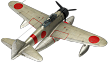
The A6M2-N, officially designated the Type 2 Floatplane Fighter Model 11, represents a unique and often overlooked adaptation of one of Japan’s most iconic aircraft of the Second World War—the Mitsubishi A6M “Zero.” Developed in response to the Imperial Japanese Navy’s need for air superiority in remote island regions lacking conventional airfields, the A6M2-N combined the proven performance of a carrier-based fighter with the operational flexibility of a float-equipped aircraft. This article explores the origins, development process, and technical design of the A6M2-N, as well as the strategic circumstances that led to its creation. By examining both its engineering challenges and its role in early Pacific War operations.
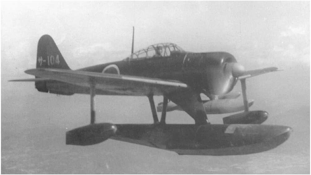
Table of Contents
Reason for Development
The rapid progress in aviation following the First World War led to a wave of experimental aircraft designs and expanded the role of airplanes in naval warfare. Nations surrounded by water began developing float-equipped aircraft that could operate from the sea or be launched by catapults mounted on warships. These aircraft were primarily intended for reconnaissance and defensive missions against surface ships and submarines, and it was widely believed that this limited their potential. Japan, however, stood apart in its broader use of floatplanes. While other countries had explored the concept, Japan was the first to successfully design, mass-produce, and deploy a float-equipped fighter in combat.
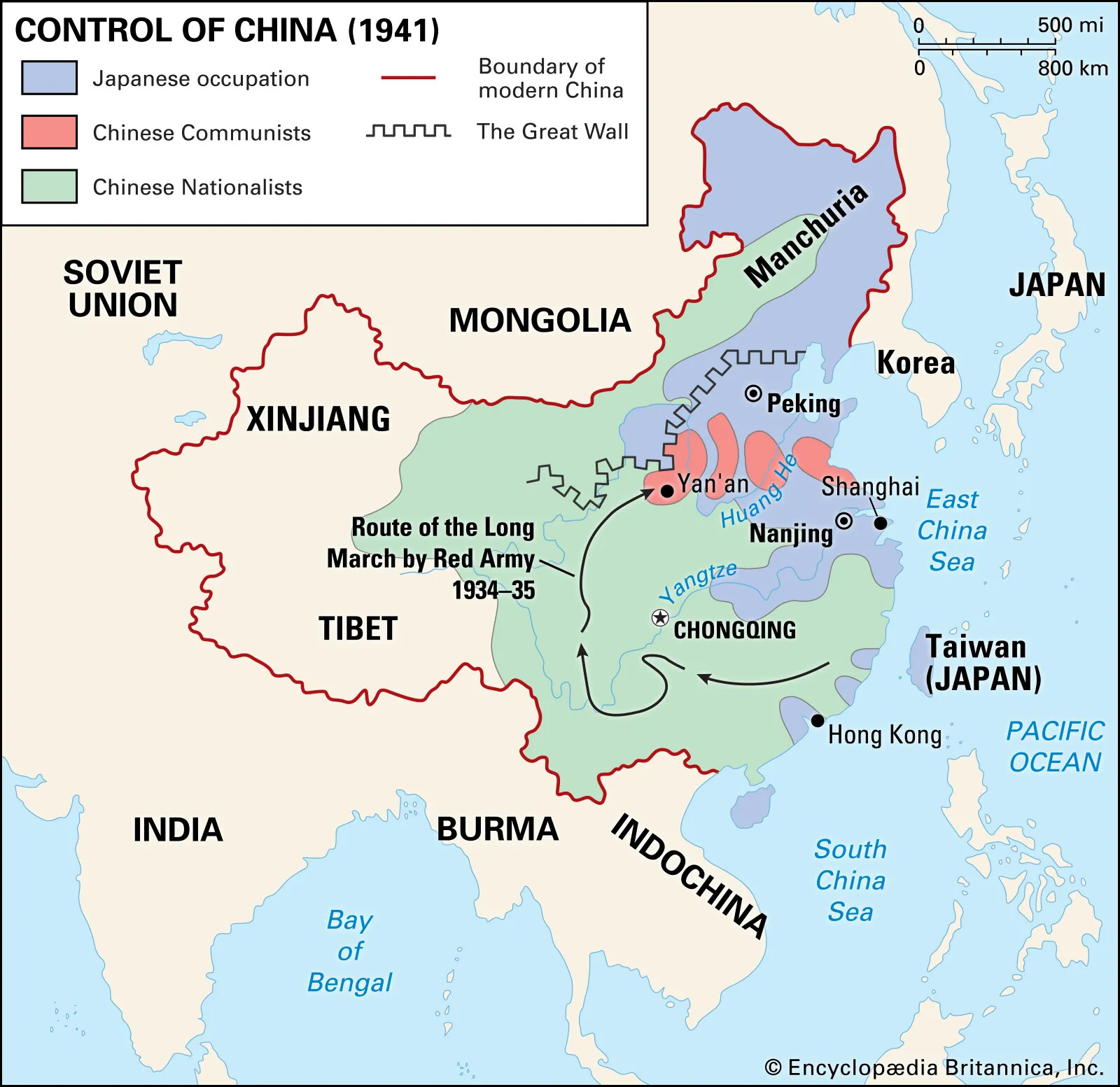
During its campaign in China, Japan’s naval air forces quickly achieved air superiority, demonstrating their effectiveness. At the same time, the conflict highlighted Japan’s growing dependence on critical raw materials such as oil, rubber, and iron ore to sustain its war efforts. These resources were abundant in the islands of the southwest Pacific, which were relatively easy to seize but politically dangerous targets, as doing so would likely bring Japan into conflict with Great Britain, the Netherlands, and the United States. Japanese planners understood that once these islands were captured, they would become forward bases for continued operations, requiring airfields to support them. While the Allies already operated airfields on larger islands, Japan also intended to use smaller islands and atolls in less defended areas. Because of the vast distances involved, aircraft carriers could only support a limited number of operations at any one time, making it essential for amphibious landing forces to have immediate air cover even before land-based airfields could be constructed. Additionally, fleet units conducting offensive operations needed protection during maneuvers across the Pacific.
To meet these needs, the Navy Air Headquarters (Kaigun Koku Hombu) issued the “15-Shi” specification in September 1940 for a float-equipped fighter capable of operating from small islands and atolls unsuitable for conventional airfields. The design called for a single-seat, single-engine fighter powered by a radial engine, equipped with one main float and two smaller stabilizing floats. The contract was awarded to Kawanishi, which was expected to produce a workable design quickly. The company assigned the project, designated N1K1 ( 強風 ) , to a team of engineers including Toshihara Baba, Shizuo Kikuhara, Hiroyuki Inoue, and Elizaburo Adachi. Despite their enthusiasm, the prototype proved difficult to develop.
The original plan involved a powerful 1,460-horsepower Mitsubishi engine driving a pair of contra-rotating two-bladed propellers, but persistent gearbox issues caused major delays. As the likelihood of war increased, the Navy grew impatient, especially since a finalized design had yet to emerge. After more than eighteen months, the contra-rotating propeller system was abandoned in favor of a simpler three-bladed propeller. When the N1K1 prototype finally flew in May 1942, its performance was satisfactory, but Kawanishi lacked the production capacity to manufacture it in large numbers. Ultimately, only eight prototypes and 89 production aircraft were completed.
While development of the N1K1 continued, time pressures forced the Navy to explore an alternative approach: converting an existing fighter into a floatplane. At that point, the most capable fighter in the Imperial Navy was the Mitsubishi A6M2 Model 21 ( 零式艦上戦闘機 ) , which had dominated opposing aircraft during operations in China. It was decided to adapt this aircraft into a float-equipped version that met the original “15-Shi” requirements, along with additional modifications outlined in the “16-Shi” specification. Because Mitsubishi was already operating at full capacity, the task was assigned to Nakajima Hikoki K.K. in Ota. Nakajima had recently begun producing the Zero under license and had both the facilities and design resources necessary to carry out the conversion.
Development and Design of the A6M2-N Floatplane Fighter
In February 1941, engineers Niitake and Tajima began work on a project designated AS-1. At the time, Nakajima was primarily producing aircraft for the Japanese Army and had already achieved success with fighters such as the Ki-27 ( 九七式戦闘機 ) and Ki-43 ( 一式戦闘機「隼」). Although the company had designed the highly effective B5N ( 中島 ) torpedo bomber for naval use, that aircraft employed a conventional wheeled landing gear. Converting a frontline fighter into a floatplane therefore posed a significant challenge, requiring the engineers to revisit and analyze the long-neglected research notes of earlier designers. Where the project required adapting a lightweight, land-based fighter, for water operations by adding a large central float and wing tip pontoons. This increased weight and drag, creating complex aerodynamics and stability issues that needed to be resolved.
After evaluating several options, the team concluded that the Mitsubishi A6M2 was an excellent candidate for conversion to floatplane configuration, as only minimal structural changes would be required. The primary task lay in designing suitable floats and determining the most effective method of attaching them. The resulting aircraft retained most of the original design and was designated the A6M2-N.
Wings and Armaments
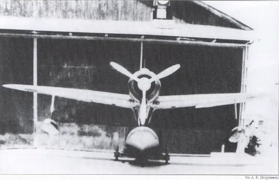
The wings were of fixed construction and consisted of two main spars and thirty ribs. They featured a dihedral angle of 5°40′ and a tapered, rounded planform, with each wingtip containing two ribs. For structural reasons, the spars were not made as single pieces but were joined between the 12th and 13th ribs using angle plates, screws, and rivets. Longitudinal members were added to reinforce the skin. Each wing housed two fuel tanks and was covered with smooth, flush-riveted duralumin stress skin.
The ailerons, measuring 3,283 m in length, were metal-framed and fabric-covered, equipped with trim tabs, and attached to the rear spar by three hinges. Split flaps of metal construction with wooden reinforcement at the trailing edge, each 1,595 m long, were also mounted to the rear spar. Armament consisted of two 20 mm Type 99 20 mm No. 1 Fixed Machine Gun Model 3 ( 九九式二十粍一號固定機銃三型 ) installed in the wings, each supplied by a 60-round drum magazine accessible through panels on the upper wing surfaces.
Beneath the wings, adjacent to the cannons, were two racks capable of carrying 60 kg bombs. The conventional landing gear was completely removed, and the wheel wells were faired over. Two cantilever stabilizing floats were mounted beneath the wings at approximately one-third of the distance from the wingtips. Once completed, the wing assemblies were attached to the fuselage, with the wing skin forming the cockpit floor.
Engine
The fuselage followed the same basic three-section layout as the standard A6M2. The forward section housed the Nakajima Sakae 12 ( 栄一二型 ) , a fourteen-cylinder, air-cooled radial engine delivering 953 horsepower for takeoff. A supercharger, driven through step-up gearing from the engine shaft, supplied the correct pressure to the intake manifold.
The engine was mounted to a ring-shaped bearer frame of welded tubing, which featured thirteen engine attachment points and was connected to the firewall by four welded V-shaped struts, each secured with a 16 mm flange. The carburetor intake was positioned at the base of the engine cowling. Propulsion was provided by a three-bladed Sumitomo propeller—built under license from Hamilton Standard—with a diameter of 2.9 m and a pitch adjustable between 25° and 45°.
The remainder of the fuselage can be divided into forward and rear sections, both reinforced by four solid longerons flush-riveted to the outer skin. The forward fuselage, extending from the firewall to former number 7 at the wing trailing edge, was of semi-monocoque construction with stressed skin incorporating molded channels that served as several internal formers. This section housed the pilot’s seat and rollover structure, with additional stiffness provided by duralumin stringers.
It was joined to the wing structure during factory assembly, with formers number 4 and number 7 connected directly to the main wing spars. Former number 7 featured eighty holes for 5 mm screws to secure the rear fuselage section. Two 7.7 mm Type 97 machine guns were mounted above the tanks, each fed by a 500-round belt. Their mechanisms extended through the firewall into the cockpit, allowing the pilot to clear jams more easily. Behind the firewall were located the main fuel tank and a 60-L oil tank, bringing total fuel capacity to 518-L; neither tank was self-sealing.
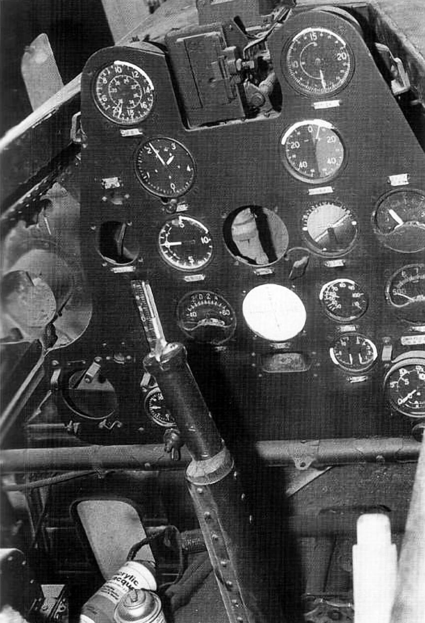
Cockpit
The cockpit was positioned between formers number 2 and number 5. The pilot sat in a vertically adjustable seat stamped from duralumin. Behind the seat were the oxygen bottles, a Type 96 Ku-1 radio with a range of approximately 90 km, and a Type 1 Ku-3 battery-powered radio direction-finding unit. Flight and engine instruments were mounted on the main panel, while a manual fuel pump was located to the pilot’s right. Aircraft controls consisted of a single control stick and rudder pedals. The cockpit enclosure was made of organic glass and slid rearward for access.
A Type 98 reflector gunsight was installed behind the windscreen, and the weapon trigger was integrated into the throttle control.
Fuselage
Toward the rear, the fuselage tapered to an oval cross-section and merged into the tail assembly at former number 16. Modifications in this area included the removal of the tail wheel and arresting hook and the addition of a stabilizing fin. The fuselage terminated in a two-piece tail cone that extended the contour of the vertical fin.
The tail assembly was cantilevered and fixed in place, with the exception of the elevator leading edges. Control surfaces were metal-framed, fabric-covered, and actuated by cable systems. The rudder featured a symmetrical airfoil and was mounted at a right angle to the fuselage, attached to former number 16 by three hinges and fitted with a trim tab. The horizontal stabilizer was of twin-spar construction with a span of 4.7 m and was set at an incidence of 1°. The elevators, also metal-framed and fabric-covered, included trim tabs and were hinged to the rear spar.
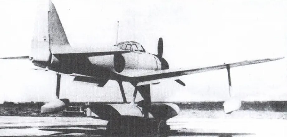
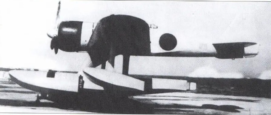
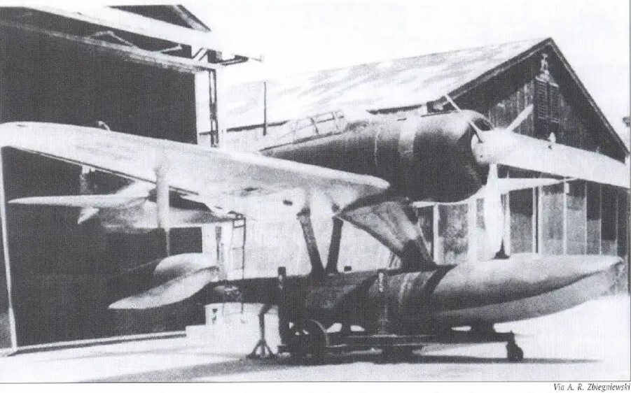
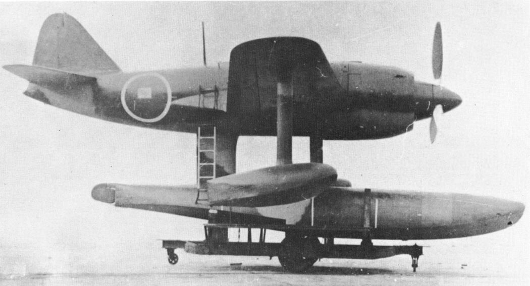
Float
The most visually distinctive change was the installation of a large central float beneath the fuselage. Constructed entirely of metal, it was divided internally by bulkheads reinforced with stringers. Its upper section was oval in cross-section, while the lower portion consisted of two concave halves meeting along the aircraft’s centerline. Stabilizing fins were fitted at the lowest points and at the rear of the float. Within its central section was a 330-L fuel tank, replacing the ventral fuel tank used on the carrier-based A6M2. The float was secured to the fuselage by a robust forward mounting structure.
The main float was secured by a robust forward pylon and a slimmer, V-shaped rear strut. The forward pylon contained an air intake for the oil cooler, which was located behind the engine firewall, as well as the fuel lines supplying the float-mounted fuel tank. The rear V-shaped strut was positioned at a right angle to the cockpit and aligned with the rear bulkhead.
Completion and first flight
The prototype was completed in late November 1941 and made its first flight on December 8, 1941 (December 7 in Hawaii), the same day hostilities began in the Pacific. Early flight tests showed that modifications to the main float were necessary to improve the stabilizing effect of its fins. As a result, three additional prototypes were constructed and subjected to intensive testing through March 1942.
The added weight and aerodynamic drag reduced the aircraft’s maximum speed to approximately 440 km/h. Despite this loss in speed, the floatplane maintained the agility and stability of the original fighter, and the Navy Air Headquarters (Kaigun Koku Hombu) was highly satisfied with its performance. Since Allied bombers and reconnaissance aircraft were generally slower, the float-equipped fighter was considered fully capable of intercepting them. Consequently, the A6M2-N was approved for production under the designation Type 2 Floatplane Fighter Model 11, also known as the Ni-Shiki Suijō Sentōki.
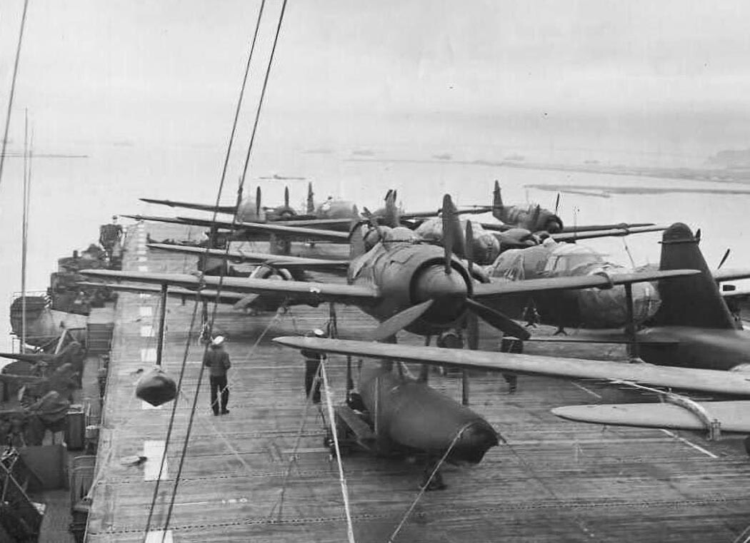
The only significant change introduced during production was the adoption of a more conical propeller. The exact number of aircraft fitted with this propeller is unknown, though estimates suggest it did not exceed 120 units. Production rates gradually increased to around 15 to 20 aircraft per month. By the time manufacturing ended in September 1943, a total of 327 A6M2-N's had been completed. These aircraft served with numerous naval air groups, including those based at Kajima, Otsu, Sasebo, Toko, and Yokohama, as well as the 5th, 14th, 36th, 452nd, 801st, 902nd, and 934th Kokutai, in addition to the Kamikawa Maru Suisentai.
Production officially began in April 1942, initially limited to twelve aircraft per month. Half of the early production aircraft were deployed to the Aleutian Islands, while the remainder were sent to the Solomon Islands. Further development of the A6M2-N was not pursued aggressively, as it was widely believed that the Kawanishi N1K1 “Kyōfū” would soon enter service as its replacement. It was anticipated that pilots and ground crews trained on the A6M2-N could be rapidly transitioned to the newer aircraft. In reality, by the time the Kyōfū reached production, Japan had already largely lost control of the Pacific theater.
Britannica Editors. (2025, December 8). Second Sino-Japanese War | Summary, combatants, facts, & Map. Encyclopedia Britannica. https://www.britannica.com/event/Second-Sino-Japanese-War
Francillon, R.J. Japanese Aircraft of the Pacific War. London:Putnam, 1970.Francillon, R.J. Japanese Aircraft of the Pacific War. London:Putnam, 1970. ISBN 0-370-00033-1.
Janowicz, Krzystof. Mitsubishi A6M2-N Rufe (Kagero Famous Airplanes 4) (in Polish/English). Lublin, Poland: Kagero, 2004. ISBN 83-89088-42-8.
https://www.airwar.ru/enc/fww2/n1k.html
The Information Architects of Encyclopaedia Britannica (2026, February 26). Second Sino-Japanese War. Encyclopedia Britannica. https://www.britannica.com/facts/Second-Sino-Japanese-War