Difference between revisions of "Turbojet engine"
Inceptor57 (talk | contribs) (Transfer Mechanics page - Turbojet) |
(Edits.) |
||
| Line 5: | Line 5: | ||
[[File:TurboJetEngine_Jumo004B_PowertoAltitudeTable.jpg|thumbnail|right|Fig.2: Jumo 004B - power to altitude table]] | [[File:TurboJetEngine_Jumo004B_PowertoAltitudeTable.jpg|thumbnail|right|Fig.2: Jumo 004B - power to altitude table]] | ||
| − | The typical speed characteristics for a turbojet engine can be seen on fig.1 and 2 (VK-1 and [[Me_262_A- | + | The typical speed characteristics for a turbojet engine can be seen on fig.1 and 2 (VK-1 and [[Me_262_A-1a|Jumo 004B]]). The graphs show that when the flight speed increases, the thrust first decreases, then increases and then at М (Mach) 2...4 falls to zero again. This type of change in thrust depends on changes to some of the main parameters of the turbojet engine: the extent of increases in pressure, air consumption, unit thrust, etc. |
The unit thrust of a turbojet engine (Rsp, fig.3) constantly falls as flight speed increases, because it is determined by the difference in the speed of exhaust gas flow and the flight speed (when the flight speed and the speed of exhaust gas are equal, the engine obviously does not produce thrust). | The unit thrust of a turbojet engine (Rsp, fig.3) constantly falls as flight speed increases, because it is determined by the difference in the speed of exhaust gas flow and the flight speed (when the flight speed and the speed of exhaust gas are equal, the engine obviously does not produce thrust). | ||
Latest revision as of 02:27, 18 January 2019
The velocity characteristic of a turbojet engine is the dependence of engine power on the true M (Mach - speed of sound) airspeed value at a constant H (height) according to the engine speed control law. It was only possible to regulate early turbojet engines that had a fixed flow channel shape by changing the level of fuel consumption. This is why, under these conditions, the speed control law is implemented through maintaining a stable number of engine revolutions and a constant temperature of the gases that leave the combustion chamber.
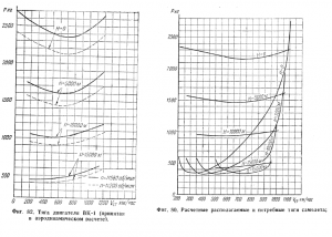
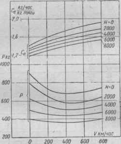
The typical speed characteristics for a turbojet engine can be seen on fig.1 and 2 (VK-1 and Jumo 004B). The graphs show that when the flight speed increases, the thrust first decreases, then increases and then at М (Mach) 2...4 falls to zero again. This type of change in thrust depends on changes to some of the main parameters of the turbojet engine: the extent of increases in pressure, air consumption, unit thrust, etc.
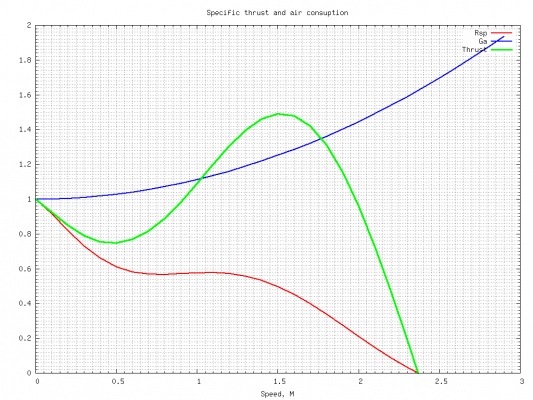
The unit thrust of a turbojet engine (Rsp, fig.3) constantly falls as flight speed increases, because it is determined by the difference in the speed of exhaust gas flow and the flight speed (when the flight speed and the speed of exhaust gas are equal, the engine obviously does not produce thrust).
The amount of pressure increase and the great flow of air related to it (Ga, fig.3) increase as speed increases (the higher the speed the more air flows through the engine as a result of dynamic pressure). At low flight speeds, the growth in pressure and air flow is insignificant but becomes a lot higher as speed increases (the relation is close to being quadratic).
As a result, the thrust of the turbojet has several specific characteristics – at low speeds, the thrust is reduced to speeds of approximately 0.5...0.6 of М (Mach) because of the faster reduction in unit thrust in relation to the rise in pressure, and then the thrust grows as a result of the faster growth in pressure and airflow, after this the thrust again falls to zero.
The engines of most early jet aircraft were located inside the body of the plane due to their great size in comparison with the aircraft itself. This resulted in additional difficulties with supplying air to the engine. Also, a significant proportion of compressed air was taken after the engine compressor for supplying pneumatic systems and devices and maintaining a constant air pressure in the pressurized cockpit. Power from the engine was also used for oil pumps and electricity generators. All of these additional factors lead to a reduction in the thrust of the engine installed on an aircraft in comparison to the thrust obtained on a test bed which is usually what is written in reference books. For example, the thrust of the VK-1 engine of the MiG-15bis is 2500 kg at a speed of zero at sea level, while when the same engine is on a test bed under the same conditions, it has a thrust of 2700kg (see fig.1). In flight, due to the decrease in unit thrust at small speeds, the thrust of the VK-1 installed in an aircraft decreases to 2150 kg at sea level, which is 80% of its thrust when it is static on a stand.


