This article will guide you through introducing thrust vector control (TVC) into your custom aircraft model, whether in two-dimensional or three-dimensional configurations. TVC enhances an aircraft's flight performance, especially in scenarios where standard control surfaces become less effective, such as at low speeds near stall conditions or at high altitudes in thin atmospheres.

As of this writing, the game does not feature aircraft with this mechanic (excluding vertical takeoff and landing (VTOL) aircraft). However, the capabilities for its implementation, as well as parameters affecting aircraft behavior in flight, already exist. Let's begin.
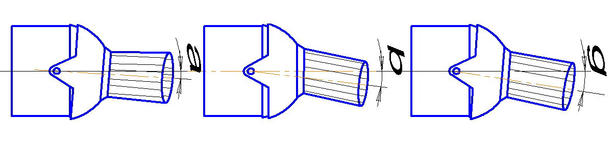
As an example, let's consider the simplest variant of an all-aspect nozzle with mechanical TVC, where the entire nozzle mechanism deflects rather than individual vanes.
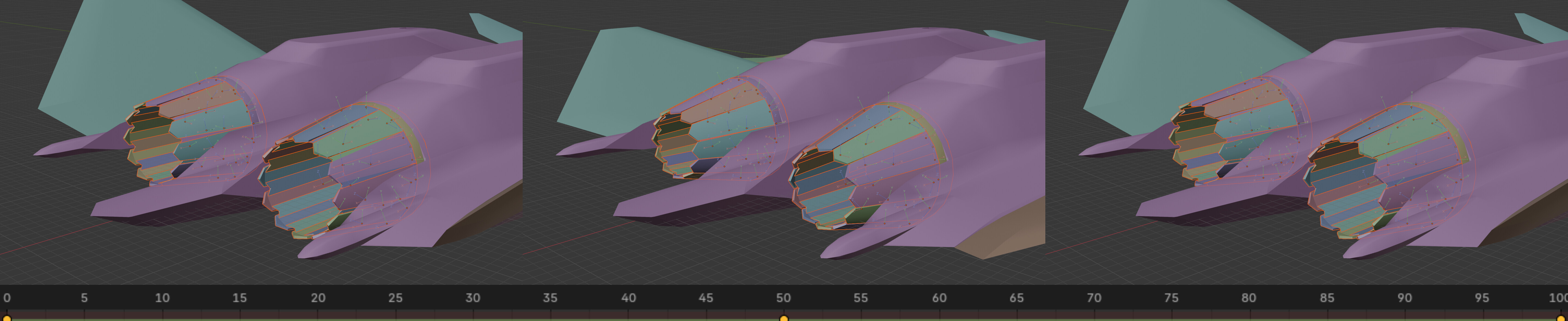
To start, it would be beneficial to animate the nozzle vanes. The method depends on your model's rigging; in my case, each vane rotates around its local Z-axis. By using Orientation: Local and Insert Keyframe with Keying Set: Rotation, I managed this quickly.
It's sufficient to set keyframes at three frames:
- 0 — afterburner engaged
- 50 — engine off (0% throttle)
- 100 — maximum thrust (100%)
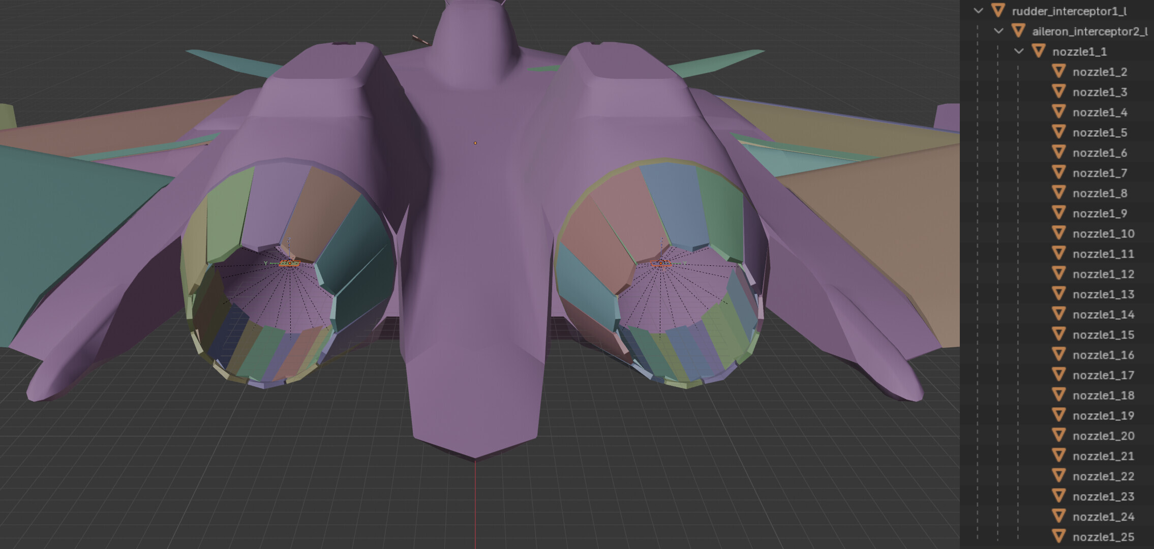
Regarding the hierarchy, for the left engine (No. 1), the vanes and other parts of the nozzle are named sequentially: nozzle1_1, nozzle1_2, ... nozzle1_25. For the right engine (No. 2), the scheme is similar: nozzle2_1, nozzle2_2, ... nozzle2_25. It's simple and clear.
Now, onto TVC. For animation, we'll use interceptors; they are notable because they allow frame-by-frame animation for control surfaces, whereas regular ailerons or rudders use procedural animation. Additionally, they lack a damage model (DM), so the nozzle won't detach in flight.
TVC Animation
At the gimbal point of the mechanism (which can be determined "by eye" or from a diagram), create a plane. Name it rudder_interceptor1_l for the left engine and rudder_interceptor1_r for the right engine. Then, duplicate the objects using Shift-D and name them aileron_interceptor1_l and aileron_interceptor1_r, respectively. For the animation to work correctly, the aileron_interceptor should be a child of the rudder_interceptor.
Hierarchy:
Select the entire nozzle mechanism and make the plane aileron_interceptor1_l the parent object using Ctrl-P. The resulting structure looks as follows:
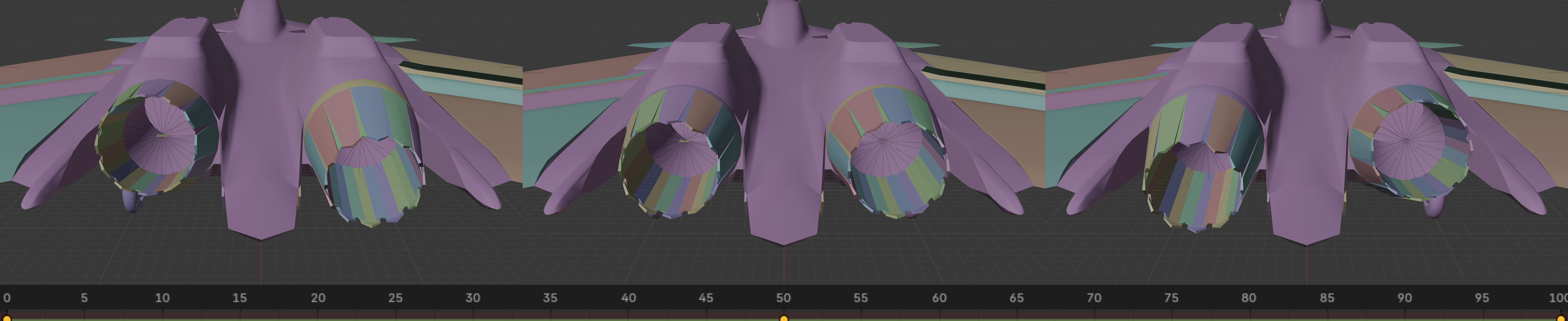
Now we can proceed to animation. At frame 50, set the interceptors to the neutral position.
In my model, the nozzles deflect:
Horizontally by 8°:.
- 0th frame — deflection to the left,
- 50th frame — neutral position,
- 100th frame — deflection to the right.
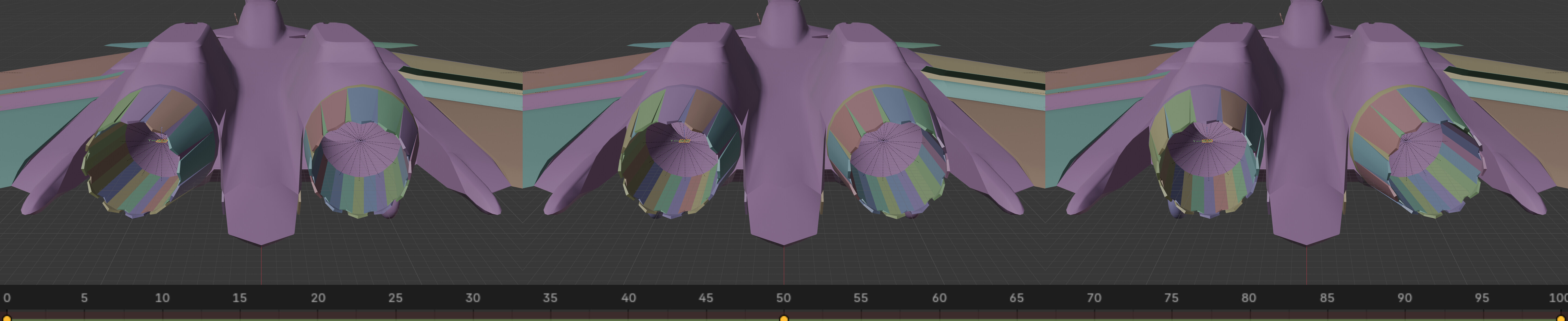
Vertically by 10°:
- 0th frame — roll counterclockwise,
- 50th frame — neutral position,
- 100th frame — roll clockwise.
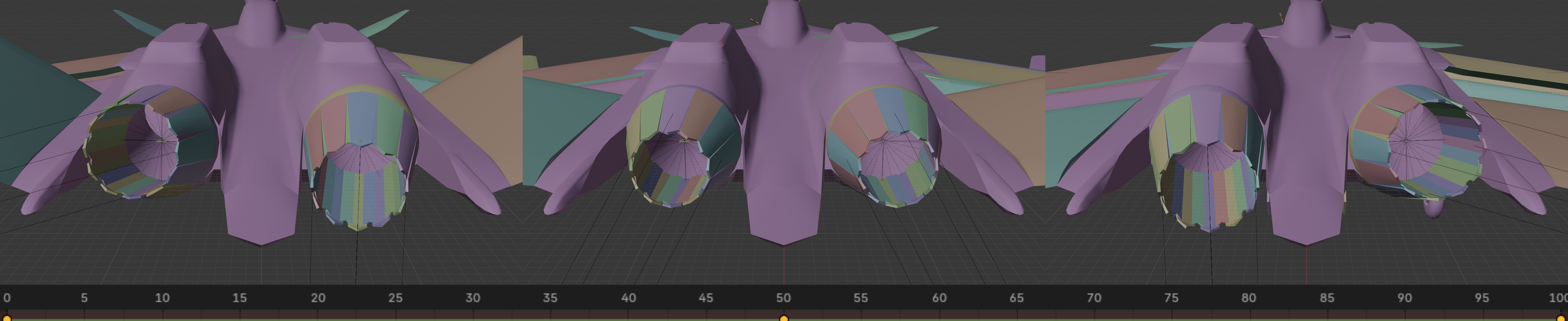
In the game, each nozzle is animated separately, so pseudo-interceptors work for roll and pitch.
To display the effects correctly, add child objects jet_flame1 and jet_flame2 to the nozzle mechanism. It's important to ensure that the X-axis of these objects is aligned along the direction of the jet stream, as this ensures the correct orientation of visual effects.
The final animation should look as follows:
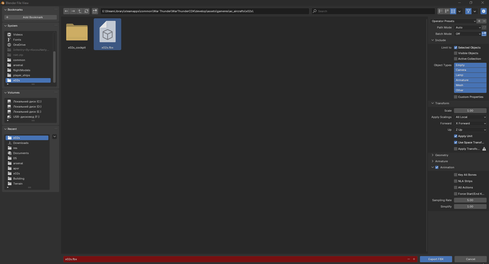
All that's left is to apply the null material to all pseudo-planes and export the file in MAX format.
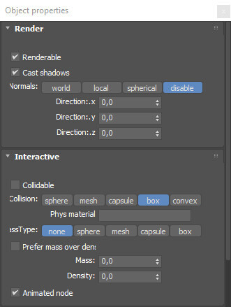
Import the file into 3Ds Max, apply the Smooth modifier to all objects, and configure the ObjectProperties parameters:
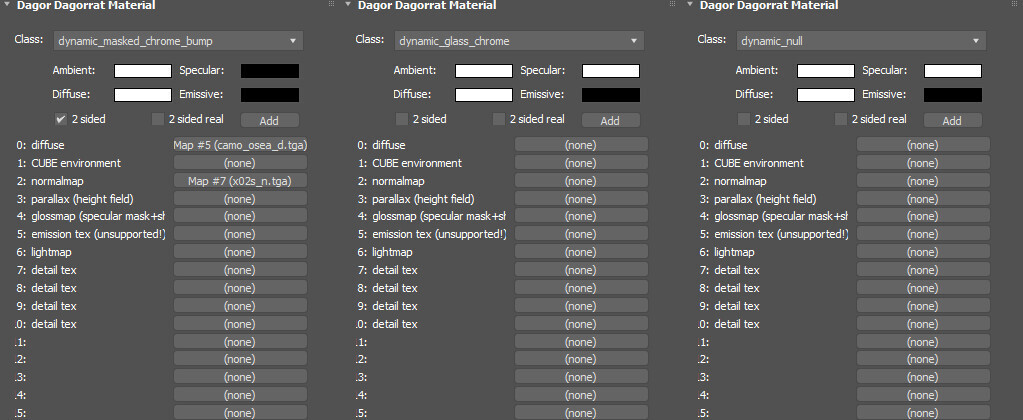
Apply Dagor2 materials:
Add keyframes to the Note track of the gear_l object (I used the Copy/Paste Note Track functionality of the Dagor Utility tool):

Export the necessary LODs and files to the AssetViewer directory, and export them to the game.
The next steps vary depending on whether you have a ready-made aircraft file and flight model (FM) or not. If not, using the links in this tutorial, you can easily obtain the F-15 or Rafale files. All that's left is to replace the aircraft .blk name, the flight model .blk, promptly fix all links to the FM file, and, just in case, restart the game.
Now, open the .blk FM of your aircraft and locate the following parameters:
  Ailerons{
    AnglesRoll:p2=25.0, 25.0
    AnglesMultiplierRoll:p3=1.0, 0.0, 1.0
    AnglesPitch:p2=0.0, 0.0 /* Сопло отклоняется только для крена */
    AnglesMultiplierPitch:p3=1.0, 0.0, 1.0
    AnglesYaw:p2=0.0, 0.0
    AnglesMultiplierYaw:p3=1.0, 0.0, 1.0
    Sensitivity:r=0.08
    SensitivityMultiplier0:p2=0.0, 1.0
    SensitivityMultiplier1:p2=0.2, 1.2
    SensitivityMultiplier2:p2=0.7, 1.0
    SensitivityMultiplier3:p2=0.95, 0.6
    SensitivityMultiplier4:p2=1.0, 0.4
    ArcadeSensitivityMultiplier:r=1.0
    SensitivityCl:p2=0.003, 0.003
    SensitivityCd:p2=0.015, -0.015
    SensitivityWingAoa:r=0.0
  }
Find the parameter AnglesPitch:p2. Modify it to define the deflection angle, similarly to how you would for roll:
  Ailerons{
    AnglesRoll:p2=25.0, 25.0
    AnglesMultiplierRoll:p3=1.0, 0.0, 1.0
    AnglesPitch:p2=25.0, 25.0 /* Теперь отклоняется во время тангажа, со скоростью как и для крена */
    AnglesMultiplierPitch:p3=1.0, 0.0, 1.0
    AnglesYaw:p2=0.0, 0.0
    AnglesMultiplierYaw:p3=1.0, 0.0, 1.0
    Sensitivity:r=0.08
    SensitivityMultiplier0:p2=0.0, 1.0
    SensitivityMultiplier1:p2=0.2, 1.2
    SensitivityMultiplier2:p2=0.7, 1.0
    SensitivityMultiplier3:p2=0.95, 0.6
    SensitivityMultiplier4:p2=1.0, 0.4
    ArcadeSensitivityMultiplier:r=1.0
    SensitivityCl:p2=0.003, 0.003
    SensitivityCd:p2=0.015, -0.015
    SensitivityWingAoa:r=0.0
  }
With the visual component completed, we can move on to the flight model (FM) behavior. Locate the nozzle parameters:
Engine0{
  Type:i=0

  Main{
    FuelSystemNum:i=0
  }

  Nozzle0{ /* -x */
    Position:p3=-10.1, 0.0, 0.962
    Direction:p2=0.0, 0.0
    Direction2:p2=0.0, 0.0
    ThrustRatio:r=1.0
    ThrustMax:r=3000000000.0
    TipPosition:b=no
    AileronsToThrustDeflection:p3=0.0, 0.0, 0.0
    ElevatorToThrustDeflection:p3=0.0, 0.0, 0.0
    RudderToThrustDeflection:p3=0.0, 0.0, 0.0
    VtolToThrustDeflection:p2=0.0, 0.0
    ReverseToThrustDeflection:p2=0.0, 0.0
    AileronsToThrust:p3=0.0, 0.0, 0.0
    ElevatorToThrust:p3=0.0, 0.0, 0.0
    RudderToThrust:p3=0.0, 0.0, 0.0
    AirbrakeToThrust:p2=0.0, 0.0
    VtolToThrust:p2=0.0, 0.0
    ReverseToThrust:p2=0.0, 0.0
    FlapsToThrust:p4=0.0, 1.0, 1.0, 1.0
  }
}

Engine1{
  Type:i=0

  Main{
    FuelSystemNum:i=0
  }

  Nozzle0{ /* +x */
    Position:p3=-10.1, 0.0, -0.962
    Direction:p2=0.0, 0.0
    Direction2:p2=0.0, 0.0
    ThrustRatio:r=1.0
    ThrustMax:r=3000000000.0
    TipPosition:b=no
    AileronsToThrustDeflection:p3=0.0, 0.0, 0.0
    ElevatorToThrustDeflection:p3=0.0, 0.0, 0.0
    RudderToThrustDeflection:p3=0.0, 0.0, 0.0
    VtolToThrustDeflection:p2=0.0, 0.0
    ReverseToThrustDeflection:p2=0.0, 0.0
    AileronsToThrust:p3=0.0, 0.0, 0.0
    ElevatorToThrust:p3=0.0, 0.0, 0.0
    RudderToThrust:p3=0.0, 0.0, 0.0
    AirbrakeToThrust:p2=0.0, 0.0
    VtolToThrust:p2=0.0, 0.0
    ReverseToThrust:p2=0.0, 0.0
    FlapsToThrust:p4=0.0, 1.0, 1.0, 1.0
  }
}
The important lines here are:
AileronsToThrustDeflectionElevatorToThrustDeflectionRudderToThrustDeflection
Each of these parameters has three values:
- Negative deflection angle in degrees.
- Neutral position.
- Positive deflection angle of the jet stream controlled by the surfaces.
These parameters are rare but are very similar to the VtolToThrustDeflection parameter used for VTOL aircraft.
Enter the appropriate values according to your model:
Engine0{
  Type:i=0

  Main{
    FuelSystemNum:i=0
  }

  Nozzle0{ /* -x */
    Position:p3=-10.1, 0.0, 0.962
    Direction:p2=0.0, 0.0
    Direction2:p2=0.0, 0.0
    ThrustRatio:r=1.0
    ThrustMax:r=3000000000.0
    TipPosition:b=no
    AileronsToThrustDeflection:p3=-10.0, 0.0, 10.0
    ElevatorToThrustDeflection:p3=-10.0, 0.0, 10.0
    RudderToThrustDeflection:p3=-8.0, 0.0, 8.0
    VtolToThrustDeflection:p2=0.0, 0.0
    ReverseToThrustDeflection:p2=0.0, 0.0
    AileronsToThrust:p3=0.0, 0.0, 0.0
    ElevatorToThrust:p3=0.0, 0.0, 0.0
    RudderToThrust:p3=0.0, 0.0, 0.0
    AirbrakeToThrust:p2=0.0, 0.0
    VtolToThrust:p2=0.0, 0.0
    ReverseToThrust:p2=0.0, 0.0
    FlapsToThrust:p4=0.0, 1.0, 1.0, 1.0
  }
}

Engine1{
  Type:i=0

  Main{
    FuelSystemNum:i=0
  }

  Nozzle0{ /* +x */
    Position:p3=-10.1, 0.0, -0.962
    Direction:p2=0.0, 0.0
    Direction2:p2=0.0, 0.0
    ThrustRatio:r=1.0
    ThrustMax:r=3000000000.0
    TipPosition:b=no
    AileronsToThrustDeflection:p3=-10.0, 0.0, 10.0
    ElevatorToThrustDeflection:p3=-10.0, 0.0, 10.0
    RudderToThrustDeflection:p3=-8.0, 0.0, 8.0
    VtolToThrustDeflection:p2=0.0, 0.0
    ReverseToThrustDeflection:p2=0.0, 0.0
    AileronsToThrust:p3=0.0, 0.0, 0.0
    ElevatorToThrust:p3=0.0, 0.0, 0.0
    RudderToThrust:p3=0.0, 0.0, 0.0
    AirbrakeToThrust:p2=0.0, 0.0
    VtolToThrust:p2=0.0, 0.0
    ReverseToThrust:p2=0.0, 0.0
    FlapsToThrust:p4=0.0, 1.0, 1.0, 1.0
  }
}
Save the file and test the changes in the game. The nozzles should animate correctly, and the aircraft should not yaw or roll uncontrollably during manual control. If everything works as expected, the last step is to experiment with the aircraft’s balance and stability. If there are issues, review your files again.
Final Notes
If you have followed all the steps above, your thrust vector control system should be functional in the game. Proper testing is essential to ensure smooth and stable flight dynamics. Adjust the parameters iteratively based on in-game behavior.