3D models for aircraft
Contents
General Scene Requirements
- The scene must be fully compatible with Autodesk 3ds Max 2011
- Use lowercase Latin letters for naming scene files. No spaces are allowed. Scene and texture names cannot contain capital letters or hyphens «-». Instead, use underscores «_».
- Stacks must be collapsed on all objects (objects must be Editable Poly)
- Models are made in real scale using metric units (System units = Meters). Display units may be anything you are comfortable with.
- All objects must have their Scale reset to 100, 100, 100 (use Hierarchy/Reset Scale)
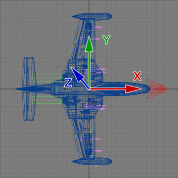
- The nose of the model must be oriented along the positive X-axis; the Z-axis should be pointed upwards; the Y-axis is pointed to the left of direction of flight.
- The scene must contain the model's initial object state (LOD0 - LOD3) and additional auxiliary geometry. Please notice that damaged model state is no longer required (DMG2_LOD0 - DMG2_LOD3). Details are provided in the appropriate sections of this document.
Layers
All objects in the scene must be composed in layers:
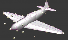
- DM - Damage Model – collision objects for an aircraft. Bullet and shell hits are calculated using these objects. They are made with simplified geometry. Aircraft collision with other objects and ground collision is made possible by clipping points. They mark the extent of certain parts of the plane: wings, fuselage etc.
- GUN - flames from gun barrels, attachment nodes for bomb and rocket payloads (see sample model for details)
- LOD0 - undamaged state LOD0. Effect emitters also go here (emitters can be found in the sample model)
- LOD1 - undamaged state LOD1
- LOD2 - undamaged state LOD2
- LOD3 - undamaged state LOD3
- pilot - the model of a pilot goes here, it is not the actual pilot model that will be visible in game. Only its pivot will be used to place the actual pilot. The size of the model is roughly the same size of the actual pilot that will be used in game.
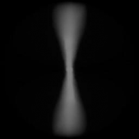
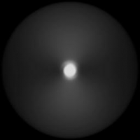
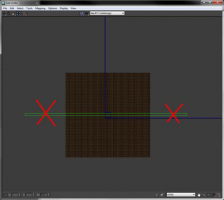
- prop_side - is a plane with the texture of propeller viewed from the side. It is only displayed when looking at the propeller from the side. When looking at different angles it fades away evenly. It is placed in its own separate layer because it does not require LODs.
- nodes_gunner - reference gunner models or gunner animation nodes go here
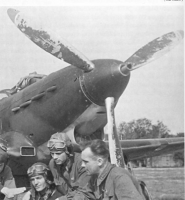
Before you start: It is a good practice to study photos and drawings thoroughly. Match drawings; with photos and select the most suitable layout. Many drawings usually have errors. There is no perfect drawin;- Only factory ones are accurate. Always choose: the drawing most similar to photographs and use them as a starting point; carefully comparing all of the shapes with photos. Select photos of an aircraft, which clearly show projection views (top, left, front etc.). Superimpose. drawings on top of them. Then, compare and make notes of any discrepancies.
Suggested modeling steps
- 1st Stage - Accurately laid out model which fits nicely into proper dimensions. At this point it is better not to weld or merge wings, engine nacelles, cabin interiors and other parts together. All parts should be separate at this stage.
- So it is easy to move parts and modify shapes in case of any error found. The fuselage must have correct shapes along its run. Wings must have correct shapes, angle of attack, twist or dihedral, if any. Same goes for propeller blades.
- The scene may include all drawings in a separate layer called «drawings». You can store all related pictures and drawings inside your model folder for easy access.
- 2nd Stage - Final geometry including details: navigational lights, landing lights, engine, pitot tube, cockpit, the interior of wings and fuselage, landing gear animation, correct placement of all pivots for moving parts, correct object naming, null-polygons done (polygons with non-renderable shader).
- The LOD0 geometry at this point should be optimized and have a “final” look.
- 3rd Stage - A fully mapped model with baked Ambient Occlusion. At this point ambient occlusion may be rough since UV-coordinates may change. The multi-material can be applied to the model, with correct material IDs. Correct IDs also have to be assigned to polygons in accordance to material.
- 4th Stage - The model with diffuse texture containing aircraft colors, paneling, riveting, access hatches, identification marks, and finalized Ambient Occlusion.
- 5th Stage - All LODs are done at this point. The model with final diffuse texture containing all of the above mentioned items plus wear and tear, aging and service labels.
- 6th Stage - Finished model with all of the textures (diffuse, normal, and specular). Including all textures for damaged state (with bullet holes).
Model
LODs and polygon count
The figures below are recommended: For complex models overhead of 5-10k is allowed.
- LOD0 – around 50-70k triangles for fighters and 60-100k for bombers
- LOD1 – around 15-23k tris for fighters and 18-33k tris for bombers
- LOD2 – around 1,500-2,000 tris
- LOD3 – up to 150 triangles
When making LODs bear in mind that LOD switching has to be smooth and the model should look good at certain distances. Here are the LOD visibility distances:
- LOD0 – 0 to 150 meters
- LOD1 – 150 to 500 meters
- LOD2 – 500 to 1,000 meters
- LOD3 – 1,000+ meters
at 90 degree FOV.
Aircraft model positioning
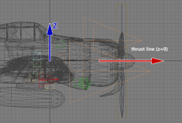
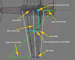
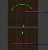
Correct positioning of the aircraft model along X and Y and Z axis is important because it influences flight dynamics. Aircraft’s center of gravity should be at world zero (0,0,0) coordinates. Usually aircraft’s symmetry axis is at Y=0 coordinates (when viewed from the top). Engine thrust line is at Z=0. And X=0 coordinate for a fixed wing aircraft with ordinary tapered wing (most common type for War Thunder timeframe) is calculated using this graphical method.
- Define a wing with a trapezoid. Sides are tip and root chord (on the axis of symmetry) and straight lines running along leading and trailing edges of the wing
- Draw 50% chord line (divides tip and root chord in half)
- Extend tip and root chords with opposite copies
- Draw a line connecting resulting extremes
- Intersection of this line and 50% chord line is where our mean aerodynamic chord is at
- Center of Gravity is usually located at 25% of the mean aerodynamic chord
When CG is found you can move the whole aircraft so CG matches X=0 coordinate.
Undamaged state
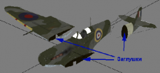
Model with undamaged texture. (Shown in Figure 1)
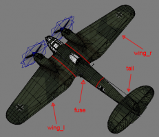
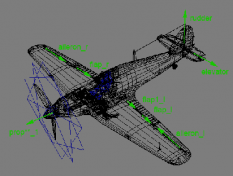
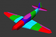
- The model must be split into 4 fixed objects: the fuselage, left and right wings, and tail. (Figure 1) This must be done in order to damage parts separately, and not the whole aircraft. The local axis (pivots) of these objects must match the world axis and be positioned at world zero (0,0,0).
- All movable parts are to be created as separate objects: landing gear, landing gear doors, bomb bays, aircraft control surfaces, ailerons, flaps, elevators and rudder, air brakes (if any), propeller spinner with blades, canopy, turrets and guns.
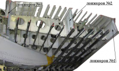
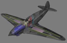
- The structural framework needs to be created inside the wings, fuselage and tail (spars, ribs, frames and stringers). Structural framework should be present in places where damage texture has large openings revealing the internal structure of the plane.
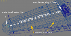
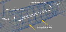
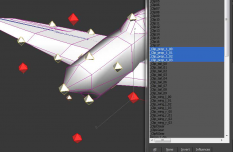
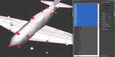
- With the introduction of new damage system internal structure should also be present between emtr_break_* emitters placed inside wings and tail parts. Parts will break off revealing the internal structure.
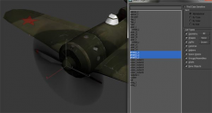
- Assign Material ID (6) to interior polygons. (figure 3) Interior texture must have «_inside» postfix. Our existing interior textures are suitable for many aircraft. But not always. If ready samples are not suitable, then a new one, specifically for your aircraft, will have to be drawn. Please do not forget about the postfix.
- Because polygons with this texture name will be hidden automatically for undamaged state in game. So naming convention should be strictly followed.(Figure 2)
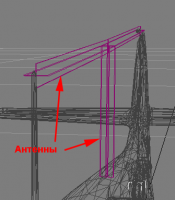
- If there are antennae or bracing wires stretching from the fuselage to the tail, they must be done as separate objects called Antenna.
- When the tail is torn off the antenna will be hidden which otherwise is not possible.
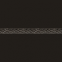
- Antennae should be made with polygons which are wider than the actual antenna. The texture with alpha channel (provided with the sample model) have some slack space for this.
- Together with blend shader this method will remove jagged edges in game modes without antialiasing.
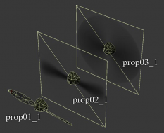
There are 3 separate meshes for an aircraft propeller.(Figure 7)
In figure 8 parts are spread apart: it looks like this:
- prop01_1 - the spinner (hub fairing) or hub itself + blades (geometry)
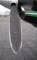
- prop02_1 - the blurred spinner or hub + a texture of radially blurred blades
- prop03_1 - the blurred spinner or hub + a texture of a greater blurred blades
Some texture samples for spinning props are provided with the sample model. In «Hangar» game mode we see prop01_1. All other geometry prop objects are hidden. When the engine is started in the game, prop01_1 begins to spin, and is replaced by prop02_1 at certain RPM. When the engine reaches operational RPM, prop02_1 is replaced by prop03_1. The numbers immediately after the word «prop» correspond to different propeller states. The number after the underscore correspond to the propeller number in the multi-engined aircraft. If an aircraft has 2, 3, or 4 propellers, the last numbers are changed accordingly.
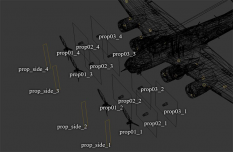
The illustration in figure 9 how the propeller objects look for the B-17 four-engined heavy bomber (objects are split apart for a better view): Billboards named prop_side show only one state. At different speeds the prop looks the same from the side. So only the last number is present and should be changed.
If there is a stripe at the tip of the blades, then it must be depicted on the blurred prop diffuse texture: (Figure 10)
In Figure 11; This is the example of an alpha channel for a 2-bladed prop: for prop_02_1 and for prop_03_1The texture size is 1024x1024.
The propeller must be modeled very thoroughly. It is a large element seen up close inside the «Hangar». Please do not hesitate to use more polys to get a smoother and more rounded detailed look.
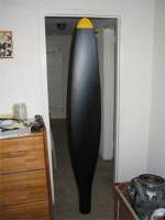
Blades can be huge: In figure 13, this shows how big some propeller blades are, in comparison to everyday objects like door ways.
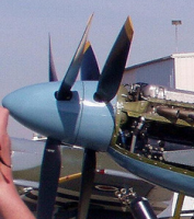
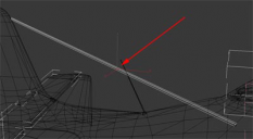
Please do not forget about the prop blades twist. The angle of attack is maximum at blade root and minimal at the tip. (Figure 14 & 15)
Additional geometry required for aircraft damaged state
Separate geometry for damaged state and severed parts are no longer required. It is replaced by automatic damage. In order for it to function properly additional emitters need to be placed in the LOD0 of the scene. These emitters are required to mark the range where cutting may occur. For wings they are:
- emtr_break_wing_l_from
- emtr_break_wing_l_to
- emtr_break_wing_r_from
- emtr_break_wing_r_to
For tail part emitters are: emtr_break_tail_from and emtr_break_tail_to. “_from” emitters are placed closer to aircraft’s center and inside the mesh. “_to” emitters are placed inside the mesh closer to perimeter.
Caps and all internal framework should have Material ID (6) assigned. Caps are placed to cover breach extremes. Tail caps may have conical shape with texture faking part depth. Wing caps may be flat.
When the part is cut off we may have some artefacts. External paint visible on internal shell because damage material is two sided. To solve this problem internal shell have to be modeled.
The easiest way is to select outer polygons in range then copy and scale down a bit and invert normals. You can use «_inside» texture for internal shell as well.
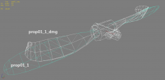
Damaged state prop have to be made for each LOD where undamaged prop01_# exist (LOD0-3). For naming just add add «_dmg» postfix to the prop name.
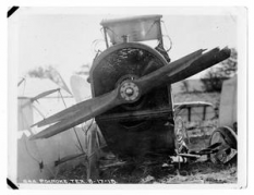
The propeller blades should be bent, as if: made of metal and broken if made of wood. Make them look as if the plane crash landed, with landing gear retracted.
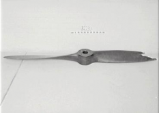
It is easy with the wooden propellers, just tear away a portion of the blades and leave some shreds:
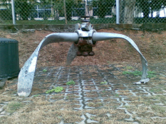
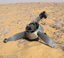
It is slightly more complicated with metallic blades. They bend when hitting the ground: then the tips twist if the propeller has high rpm when blades hit the ground.
It is important to remember that a propeller cannot be bent transversely. It bends only in spiral fashion with relation to the blade angle of attack.
UV mapping
  * All faces must be mapped and have UV coordinates
  * UV coordinates must not exceed 8x tiling in each direction
Otherwise there will be conversion errors. It is a good practice for ordinary geometry to have all mapping inside 0-1 UV space.
* All wing surfaces, fuselage, tail assembly, ailerons and flaps must be unique
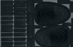
An aircraft should be uniquely mapped. With minimal or no repeats at all. It is important because an average plane has many different camo schemes which are impossible to paint if primary surfaces are mapped from the same place. An exception is made for engine parts. Cylinders, valve rods, spark plug wires and other repeating details may be mapped from one place. Texture resolution may be increased twice for cylinders and heads so that cooling ribs can be drawn with proper resolution and detail.
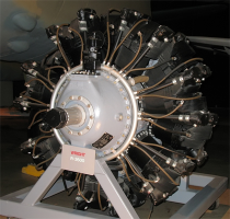
The engine may have 5, 7, or 9 cylinders in one row and there can be up to 4 rows. As you can see it is reasonable to make one cylinder with all the necessary detailing, and then clone copy it the required number of times in a circle to form a row. If the second row is not visible enough it may be replaced by a billboard.
Again a billboard should contain one cylinder and then copied required number of times in a circular pattern.
Please do not make 2 face billboards with all of the cylinders drawn on texture. As it will waste our precious texture space.
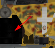
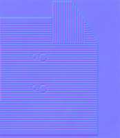
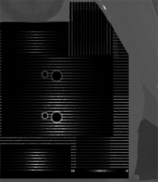
Above are diffuse, normal and specular maps.
As you can see, a single cylinder occupies roughly the same space as the vertical stabilizer of an aircraft even though the cylinder is much smaller in size. In-line water cooled engines usually are hidden under the cowling and not visible. So nothing have to be modeled. The same applies to jet engines. For the most part the detailing is not visible.
Ambient occlusion eats most of the detailing inside the air intake and exhaust. Gradually fading into dark. In some cases blades and detailing may still be visible though. It depends. If it is not eaten out by AO then it should be modeled. Jet blades can be done using 3 objects like propeller.
- Wheels of the same size and pattern may be mapped from a single place.
- Glass does not require a texture. So the scale of the mapping is not important. It may even be mapped from a couple of pixels somewhere in the corner of the texture.
- It is better to make the blades unique so that it is possible to add some nice detail like chipped paint to the edges of each blade.
To avoid this geometry can be cut into segments of the antenna layout and put on each other. pay attention. The layout of extended objects such as Antenna can go beyond the permitted limits -8 +8 UV.
To avoid this, you can cut the geometry of the antenna segments and put them on each other.
Naming and hierarchy
None of the model objects should be linked to anything. The only exceptions are the landing gear wheels which are linked to the appropriate struts. Temporary linking is allowed for making complex animations.
All such linking should be erased and animation baked in the end.
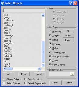
Valid object names are listed in the table below. Use lowercase Latin letters and underscores «_» for naming parts.
Aircraft parts:
| Object | Name in the scene |
|---|---|
| Fuselage | fuse |
| Left wing | wing_l |
| Right wing | wing_r |
| Tail | tail |
| Rudder | rudder |
| Left Rudder | rudder0 * |
| Right Rudder | rudder2 * |
| Elevator | elevator |
| Left elevator | elevator0 * |
| Right elevator | elevator1 * |
| Left slat | lat_l |
| Right slat | slat_r |
| Left air brake | airbrake_l |
| Additional left airbrake moving parts | airbrake_l# |
| Right air brake | airbrake_r |
| Additional right airbrake moving parts | airbrake_r# |
| Left landing gear | gear_l |
| Left wheel | wheel_l |
| Right landing gear | gear_r |
| Central landing gear | gear_c |
| Central wheel | wheel_c |
| Details of left landing gear strut | gear_l# **** |
| Details of right landing gear strut | gear_r# **** |
| Details of central landing gear strut | gear_c# **** |
| Bomb bay doors and actuators | hatch# |
| Engine # | engine# |
| Propeller #, low rpm/static | prop01_# |
| Propeller #, medium rpm | prop02_# |
| Propeller #, high rpm | prop03_# |
| Radiator doors and elements | radiator# |
| Sliding/moving canopy parts | blister# |
| Turret # | turret# |
| Machine gun on turret # | gun# |
| Flame from gun # | flare# |
| Bomb hook object # | bomb# |
| Rocket hook object # | rocket# |
| Torpedo hook object # | torpedo# |
| Bomb hardpoint # | pylon_bomb# |
| Rocket hardpoint # | pylon_rocket# |
| Torpedo hardpoint # | pylon_torpedo# |
| Aircraft arrestor hook | hook |
| Additional hook parts | hook# |
| Jet flame object | jet_flame |
| Additional jet flame objects (for aircraft with more than 1 engine) | jet_flame# |
*) – if the rudders are made of two unaligned parts **) – if there is only one flap positioned in the center (for example, on Yakovlev aircraft) ***) – if flaps have several parts on each wing ****) – all objects related to the landing gear, including landing gear doors # is replaced by natural numbers starting from 1. So we will have successive names like radiator1, radiator2, radiator3 etc. Hardpoints are named successively from left (left wing) to right. It is important to follow naming for pylons, because they are automatically hidden if the plane does not carry any payload.
Local axis
   Important notice:
      The position of pivots and local pivot orientation must completely match on all LODs for an element.
- Local axis of rudders, aerodynamic surfaces, and propeller (Figure 34)
- The direction of the Y-axis is critical for aerodynamic control surfaces. Rudders, ailerons etc. Local Y-axes should be aligned with axis of rotation and oriented according to the following drawing:
- Y-axis orientation:
- rudder – up
- elevator, flaps – to the left of the direction of flight
- ailerons – toward the aircraft’s center
- props – forward for clockwise propeller rotation and backward for counter clockwise propeller rotation
- Propellers may have different spin direction for each engine on multi engined aircraft.
- X-axis – must be pointed forward in the direction of flight
- Local axis for landing gear wheels and struts (Figure 35)
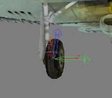
- The Y-axis should be pointed to the left of direction of flight, along the axis of wheel rotation. Orientation is given for an extended gear state.
- Landing gear struts may have any local axis orientation since gear legs are animated in 3ds max.
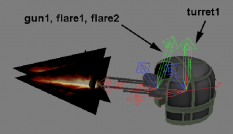
- Turrets (Figure 36)
- For all objects: X-axis is along the shooting axis, Y-axis is pointed vertically. The pivot position and orientation for the gun itself and corresponding flares must match completely.
- Meaning that flare pivot is positioned exactly in the rotation point of machine gun/cannon.
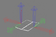
- Bomb bay doors (Figure 37)
- Bomb bay doors must open along negative Y-axis.
- Flames from nose mounted guns
- The local X-axis is set along shooting axis for flames from gun barrels. Y and Z are arbitrary.
- Other objects (stationary)
- For other stationary objects, fuselage, wings, tail, etc. pivot must be located at world zero (0,0,0) and local pivot orientation must be aligned to the world. The best practice is to reset object transforms.
The modeling of joint parts (null-polygons)
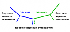
- When splitting an aircraft into separate objects many of the model's adjoining parts must retain their surface curvature (fuselage and tail, gear doors and bomb doors, wing fairings etc.)
- If objects are detached as is, then the curvature will be broken due to different vertex normals.
Labels (Figure 37)
- from left to right
- Vertex normals match
- Vertex normals differ
- Vertex normals match
- Object 1 (Displayed in Blue)
- Object 2 (Displayed in Green)
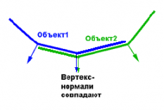
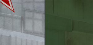
- To avoid this undesired effect, edge polygons from each part should overlap.
Labels: (Figure 38)
- Vertex normals match
- Object 1 (Displayed in Blue)
- Object 2 (Displayed in Green)
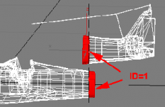
These dummy polygons must have Material ID (1). (Figure 39)
- The null-shader will be applied to those polygons and they will not be visible in game but the curvature will be preserved.
Animation
As a measure of precaution please apply Reset Scale and Reset Transform to all objects which do not require special pivot orientation before creating an animation.
Objects to animate:
- landing gear struts, doors and mechanisms
- moving and sliding canopy parts
- flaps, air brakes, interceptors
- radiator flaps and related mechanisms
- arrestor hook
- bomb bay doors and actuators
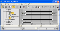
Animation is done only for LOD0. Animation should be made in the 0 to 100 frame range. A Note Track needs to be created in the “Track View - Dope Sheet” editor with keys start in frame 0 and finish in frame 100 for one of the objects. The game code reads the start and finish keys for playing the animation. Note Track for the external model is added to gear_l object. Please do not add note tracks to other objects.
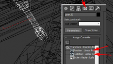
Only Linear Position, Linear Rotation and Linear Scale controllers are allowed for animated objects: (Figure 40)
There should be no Euler or other controllers. And no constraints. (Figure 41)
During the intermediate stages of animation creation process you can have any hierarchy and constraints you want. For example “LookAt” or “Orientation” constraints are particularly useful. It is difficult to create animation with linear controllers only. But in the end all animation for all animated objects should be baked. Leaving only the most simple controllers: linear motion, rotation and scale (very rarely). No hierarchy should be present. At frame 0 we have fully retracted/closed object animation. At frame 100 we have fully extended open object animation. Landing gear, doors, flaps e.t.c.
Emitters
Emitters are the spawn points for various aircraft related particle effects. Also they mark certain coordinates for game logic. Particles are spawned at the pivot point of the emitter. Emitters are provided with the sample model.
- emtr_inversion_l – for inversion trail streaming from the left wing
- emtr_inversion_r – for inversion trail streaming from the right wing
- emtr_shellrejection# – for shell casings discharge when guns are fired. Placed near shell discharge ports
- emtr_exhaust# – engine exhaust effects. Placed at the ends of exhaust pipes (end of jet nozzle)
- emtr_oil# – oil leak, oil burn effects. Placed inside of oil radiators
- emtr_fuel# – fuel leak, fuel burn effects. Placed on the surface of fuel tanks. Please see aircraft x-ray layout for fuel tank positions. Each fuel tank must have an emitter
- emtr_engine# – damaged engine on fire effects
- hook_catch – special emitter for aircraft carrier AI. Placed at the tip of the hook and parented to the hook
- emtr_break_wing_l_from, emtr_break_wing_l_to - mark left wing damage span
- emtr_break_wing_r_from, emtr_break_wing_r_to - mark right wing damage span
- emtr_break_tail_from, emtr_break_tail_to - mark tail damage span
# is replaced by natural numbers 1,2,3.. etc. Multi-engined aircraft may have multiple emtr_engine, oil and fuel emitters. One set per each engine. If exhaust pipes are grouped together then 1 emitter for a group is possible. Please see reference model for particular emitter placement examples. Emitters must be present only in the scene LOD0.
Materials (the order of material IDs)
One Multi/Sub-Object material is assigned to almost all objects in the scene. With the following Material IDs:
- (1) - null - Sub-material for null-shader
- (2) - camo or body - Sub-material for primary textures
- (3) - glass - Glass (without the diffuse texture)
- (4) - slow_prop - Low-rpm propeller (prop02.tga)
- (5) - fast_prop - High-rpm propeller (prop03.tga)
- (6) - inside - Sub-material for structural framework texture (spars, ribs, stringers, caps)
- (7) - interior - Interior texture for large aircraft. Visible for all states. Not used for fighters
- (8) - antenna - Antennae
Usually primary multi-sub material is called «aces». Different materials are allowed for separate reusable pieces of geometry like turrets, turret guns, bomb and flare hooks, jet flames etc.
Important!
- Lowering the material count for LODs (textures/shaders used) is as important as lowering polygon count.
- LOD0 and LOD1 polygons may have all range of IDs for damaged and undamaged state
- LOD2 may have only primary camo ID (2); glass ID (3) and propeller ID (4) and (5) assigned to polygons. Null shader and polygons are not necessary starting from LOD2
LOD3 must have primary camo ID2 only, assigned to all polygons Please make sure LODs use proper IDs.
Textures
Diffuse texture, normal map texture and specular map texture are used for a model. Separate texture sets for damaged and undamaged states.
- The diffuse texture for undamaged state should not have an alpha channel.
- The diffuse texture for damaged state has bullet and shell holes in the alpha channel.
- Specular map is placed in the alpha channel of a normal map texture.
Some important notes about diffuse colors. It is better not to sample diffuse colors from photos and color profiles. Lighting conditions on different photos are different. And color profiles may sometimes be wrong. Instead use trusted sources with exact color information like US Federal Standard 595 colors. In many cases text information about aircraft paint is available. For example if an aircraft was painted ANA 606 Semi-Gloss Sea Blue you can always find corresponding FS color. In our case it will be FS 25042. You can open color server page and sample this color for use with your diffuse texture. Use FS standard for consistency and accuracy purposes.
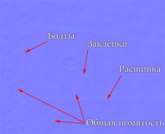
- Rivets are 1 pixel in size. It is better to draw them in gray color and then overlay with opacity or layer blend effect if necessary. Rivets should be a little lighter on painted surfaces and a little darker on bare metal (Figure 42)
Apply «Drop Shadow» or «Outer Glow» effect around rivets to create sheet metal recess effect around a rivet, since a normal map is not always clearly visible at certain angles. Paneling seams are also to be drawn 1 pixel wide with a brush to create anti-aliasing effect on tilted and curved seams. Please do not use vectors to draw lines. To prevent smearing (unless you use vector to pixel snap). Because when a vector is rasterized between pixels it will give us a blurred 2 pixel line instead of a sharp 1 pixel line. Keep in mind the materials used to make various aircraft parts, when creating textures, for example, the engine cowling and central fuselage section were mostly produced from aluminum sheet and were joined by rivets. These surfaces are usually uneven, with noticeable recess areas across the skin and around rivets and bolts.
Wings and the rear of the fuselage were often made of plywood or fabric on a frame. Rudders were almost always covered with fabric with noticeable frame ribs and recessed fabric between them.
Fabric normals should look something like this:
(Figure 48) There should be no bumps near the edges of elements wrapped in fabric. Because there is a framework beneath.
Diffuse Texture
- The diffuse texture dimension for a fighter aircraft is 2048x2048 pixels.
- The diffuse texture dimension for a large bomber aircraft is 4096x4096 pixels.
The «_inside» texture dimension usually range from 512x512 to 1024x1024 pixels. Fixed hardpoints are mapped from the primary texture. If an aircraft has detachable pylons which can be reused by other planes then separate texture is required. The size can vary from 256 to 1024 depending on the pylon size, aspect ratio of this texture may differ from 1x1 and be 2x1 for example which will result in non-square textures. Use aircraft texel for deciding upon the pylon texture size. Although it is allowed for pylons to have slightly higher texture resolution.
A full set of textures for an aircraft will look like this:
- f3f_1_usn_a.tga
- f3f_1_usn_a_dmg.tga
- f3f_1_usn_n.tga
- f3f_1_usn_n_dmg.tga
- f3f_1_inside_a.tga
- f3f_1_inside_n.tga
You can see the additional «_usn» postfix in the file name. It is required to describe camo scheme of the primary texture set. One model can have many paint schemes. Please pay attention that framework texture «_inside» lacks this additional postfix because it is shared with all camo schemes.
Postfixes for texture names:
- «_c» postfix is for textures without alpha channel
- « _a» postfix is for textures with alpha chanel
- « _n» postfix is for normal map textures with specular map inside alpha channel
A note about texture postfixes. Damaged and undamaged state textures must have same postfixes. The texture with alpha has a priority giving both textures an « _a» postfix. Even though undamaged texture is lacking the alpha channel.
You can find and examine additional textures shared by multiple aircraft in the sample model archive. When using graphics software suite with layer functionality it is better to store diffuse, damage, normal map and specular maps all in one file. The resulting combined names will be (in case of Photoshop):
- f3f_1_usn.psd
- f3f_1_inside.psd
The diffuse texture must not be «sterile». The texture for a battle-scarred machine should look worn. Paintwork can be off on wings where pilot climbs into the cockpit, scratches and chipped paint, dirt at panel overlaps, weapon and exhaust pipe smoke trails, oil streaks on the belly, etc., to emphasize that it is a combat vehicle with a high degree of artistic realism. All paneling on the aircraft should be emphasized both on diffuse, normal and specular map textures. hOWEVER, there should be no thick clearly visible seams:
[[file:wiki_paneling_seams.png|
Bare metal (for chips and wear, as well as space around bullet holes) have to be within 90-120 RGB range.
Normal and Specular Texture
The normal map and specular maps are the same size as primary diffuse texture. Normal map uses RGB channels and Specular map uses an alpha channel. Normal maps in layered source files should be present as height maps before the NormalMapFilter conversion. Converted (blue) normal maps in layers are used for minor corrections only. Use filter default settings for height to normal map conversion: Min Z = 0, Scale = 8.
The normal map Y (green) channel should not be inverted
You will get the following look (as shown in figure 49) after the NormalMapFilter conversion:
Convex parts should look as if they are «lit» from below in the green channel.
Normal and specular maps are used to imitate mid-sized irregularities: crumpled metal surfaces, ribs, fabric recess, paneling and riveting. Please note that specular of painted metal, wooden, and fabric surfaces is almost the same, because they all share the same paintwork. Specular map must emphasize paneling and riveting. They have to be visible in highlight.
- Based on previous experience following brightness values are recommended for the specular map:
- Primary surfaces (paintwork): K~65% (~110 RGB)
- Bare metal (chips, wear) K~20-40% (170-210 RGB)
- Rivets (brightest pixels): K~55-60% (120-135 RGB)
Please remember, that chips on wooden surfaces do not have as much specular compared to metal.
Tips for users with advanced graphics software suites
It is better to have 4096x4096 pixel resolution for your primary texture sources. When saving out to targas for in game use you can rescale them to 2048 for fighters. For high end graphics suite users (ex. Photoshop) you would want to keep the size of *.psd files low. Lower file sizes are more convenient to work with. Try to stay under 1GB for a 4k texture. Primary size eaters are the ordinary layers with masks. Using them on every occasion can increase the size of the file dramatically in no time. Use masks with care and only where really necessary. It is advised not to use 4k masks just to change the transparency of several pixels on a layer. Solid color fills with masks are ok. They are not size eaters. Camo schemes are best done using solid color fills with a mask. Keep reasonable layer count so any element of the texture is easily editable. Not too many but not too few. Textures must have sensible names depending on the aircraft you are doing.
Layer name suggestions:
uv – rendered UV template goes here. Should be the topmost layer. Hidden by default.
Layers with base camo colors may have FS color number in the beginning. And the basic description what this color is for.
- fs37875 inside
- fs37875 belly
- fs35164 camo
- fs25042 primary
The rest of the layers must have sensible names which are easy to understand. For your convenience.
- smoke gun 0.5cal
- smoke exhaust
- decal fin flash
- decal wing stars
Using the default layer names Layer 1, Layer 2 etc. may become uncomfortable in the long run.
Suggested layer groups:
- dmg or damage – for battle damage holes
- s – specular
- n – normals
- ao – rendered ambient occlusion
- lines – rivets and paneling
- text – text and insignia layers
- dirt – dirt layers
- volume – hand painted light/dark volumes
- decals – identification marks and service labels
- cockpit – cockpit parts
- color or c – base colors and paint schemes
- You can group diffuse colors together for a certain camo scheme:
- color_usn
- color_usmc
- color_usn_neutrality
Postfixes depend on the paint scheme you are doing.
- It is better not to rasterize text layers. So that you can correct them anytime without the need of retyping anything from scratch.
Damaged state texture
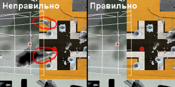
When part of an aircraft is damaged then regular textures are swapped with their damaged «_dmg.tga» counterparts. This texture is fairly easy to do. Having mastered this step it can be done within several hours together with normal and specular maps. «_dmg» postfix is added to the regular texture name. The resulting file names will be the following format: la_5_c_dmg.tga for diffuse and la_5_n_dmg.tga for normal maps. The damaged texture is the same as the standard texture, Only holes from bullets and damage from other explosives are added.
Important!
It is advised not to make any additional layers of dirt or other wear and tear inside the damaged layer group. Only the battle damage should be there. The difference between damaged and undamaged states must be ~ 20-30%, because of holes. Check in advanced image editor (with layers) if everything is ok by putting collapsed damage texture over the undamaged one with «Difference» layer blend mode. Everything except the holes must be black. Since aircraft dimensions are different and the texture size is usually the same 2048x2048 for differently sized aircraft, please make sure that absolute size of holes stays the same. I.e. holes on small aircraft are not too small, and holes on large aircraft are not too large. Keep in mind absolute size and texel.
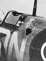
- Bullet holes should be roughly 15 to 30mm in diameter.
- Holes from explosive shells should be ~ 250-400mm.
Please do not forget to add hole transparency into the alpha channel. Transparent holes are usable in places where internal structure is done and visible: wings, stabilizer, rudder. Alpha-cut holes must not be made where internal parts do not exist. Usually it is cowling, mid fuselage and space around wing mounted guns. Although you can model any internals you would like. Please do not overuse large explosive shell holes. One or two large holes per each aircraft part is enough.
Important: It is necessary to ensure that the damaged textures do not have bullet holes in the areas where separate parts are joined together (fuselage, tail, and wings). Otherwise when one part changes its state from undamaged to damaged and the other is not we will see only half of the hole.
Reference examples:
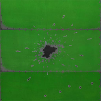
This is how a typical hole should look like on texture:
On the damage texture additional chipping to bent metal propeller blades may be added.
Ambient occlusion
An ambient occlusion layer must be rendered for a model. To have nice ambient shadows. You can use mental ray Renderer for these purposes. Select Ambient Occlusion (MR) when adding a component in the Output section of Render To Texture dialog. Use Edge Padding of 2 pixels. Following mental ray parameters are suitable for a good render:
- Samples = 96 or more
- Falloff = 10,0
Do not forget to switch to mental ray renderer in the Render Setup dialog window (F10).
- Ambient occlusion must be rendered against a white background. In advanced graphics editor use «Multiply» layer blend and place the «ao» layer group on top of the layer stack. Play with opacity as you see fit to get a good looking result.
- Please note that there will be static shadows rendered in places where we do not want them to be. On rotating wheels for example. Keep this in mind. Such places on rendered AO have to be adjusted manually. The following trick might ease this task a little. You can have multiple opaque AO layers: the initial one and correction layers on top of it. Without any transparency. Then you can change the opacity of a whole «ao» layer group to get desired look.
DM modeling
Damage Model of an aircraft is a low poly representation of aircraft hull and internal systems. It consists of geometry objects and clipping points. Geometry objects are used in hit calculations. Clipping points are used to calculate intersections with terrain and other objects and follow aircraft contours.
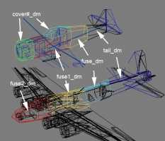
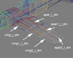
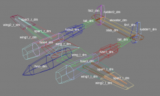
Each DM object (shell and internal parts) must have «_dm» suffix added to their names. Objects do not have to be convex because hit calculations are polygon based. This is good for modeling internal parts which may have complex shapes. Also a single object can consist of separate mesh sub-objects. For a typical fighter aircraft the DM polygon cap (excluding clips) is 3-5K triangles. For a typical bomber the cap is 4-6K triangles.
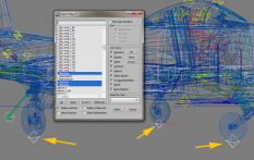
- Clipping points for different aircraft parts have respective names. (Figure 62)
Fuselage clips are placed at extreme points of the fuselage and on its surfaces. Several clips are placed on wings roughly where emtr_break_wing_#_from emitters are located. Usually at the ends of “wing_l_dm” and “wing_r_dm" parts.
Important notice:
- There should always be a root clip object _Clip present in the scene at world [0,0,0] coordinates. Pivot of any _Clip# object should be at its center.
- The numbering of _Clip# objects inside the group (fuse, wing etc.) must be continuous.
Otherwise clipping planes will not build properly and collision with ground will have artifacts.
Valid clip names and locations are:
| Clip name | Clip location |
|---|---|
| _Clip | scene root [0,0,0] |
| _ClipCGear | central wheel (tail or nose) lowest point. Or at the rear of the central float on the waterline |
| _ClipLGear | left wheel lowest point |
| _ClipRGear | right wheel lowest point |
| _ClipNGear | additional clip for central float (float planes) at the front of the central float on the waterline |
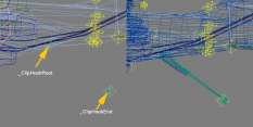
| _ClipHookRoot | arrestor hook hinge |
| _ClipHookEnd | at the extended arrestor hooks end |
| _Clip## (from 00 up to 50) | fuselage perimeter |
| _Clip_prop_1_## (from 00 up to 08) | prop_01_1 at the prop blade tips |
| _Clip_prop_2_## (from 00 up to 08) | prop_01_2 at the prop blade tips |
| _Clip_prop_3_## (from 00 up to 08) | prop_01_3 at the prop blade tips |
| _Clip_prop_4_## (from 00 up to 08) | prop_01_4 at the prop blade tips |
| _Clip_tail_## (from 00 up to 20) | tail perimeter |
| _Clip_wing_l_## (from 00 up to 20) | left wing perimeter |
| _Clip_wing_r_## (from 00 up to 20) | right wing perimeter |
Valid DM part names are:
| DM part name | Description |
|---|---|
| External shell | |
| cover#_dm (1 to 16) | parts like canopy, radomes, nacelles |
| engine#_dm (1 to 4) | aircraft engines |
| fin_dm | single tail fin config |
| fin#_dm (1 and 2) | double tail fin config |
| fuse_dm | primary fuselage part (must always be present) |
| fuse#_dm (1 to 5) | additional fuselage parts |
| stab_dm | horizontal stabilizer |
| stab#_dm (1 and 2) | additional h-stab parts |
| tail_dm | primary tail part |
| wing_l_dm, wing1_l_dm, wing2_l_dm | left wing parts. all 3 must be present |
| wing_r_dm, wing1_r_dm, wing2_r_dm | right wing parts. all 3 must be present |
| Stationary inner parts | |
| armor#_dm (1 to 10) | armor parts. glass or metal |
| cannon#_dm (1 to 8) | forward firing cannons |
| gunner#_dm (1 to 12) | turret gunners |
| mgun#_dm (1 to 12) | forward firing machine guns |
| oil#_dm (1 to 8) | oil radiators and reservoirs |
| pilot_dm | pilot |
| pilot1_dm | co-pilot |
| spar_l_dm, spar1_l_dm, spar2_l_dm | left wing primary framework. all 3 must be present |
| spar_r_dm, spar1_r_dm, spar2_r_dm | right wing primary framework. all 3 must be present |
| tailcontrol_dm | rudder and elevator control wires |
| tank#_dm (1 to 9) | fuel tanks |
| water#_dm (1 to 8) | water radiators and reservoirs |
| wingcontrol_dm | shared control wires |
| wingcontrol_l_dm | control wires going through the left wing |
| wingcontrol_r_dm | control wires going through the right wing |
| Moveable parts | |
| aileron_l_dm | left aileron |
| aileron_r_dm | right aileron |
| elevator_dm | primary elevator part (single elevator config) |
| elevator#_dm (0 to 2) | double/triple elevator config |
| rudder_dm | primary rudder part (single rudder config) |
| rudder#_dm (0 to 2) | double/triple rudder config |
| flap_l_dm | primary left flap piece |
| flap#_l_dm (1 to 3) | additional left flaps pieces |
| flap_r_dm | primary right flap piece |
| flap#_r_dm (1 to 3) | additional right flaps pieces |
| gear_c_dm | nose or tail wheel assembly |
| gear_l_dm | left gear assembly |
| gear_r_dm | right gear assembly |
| gun#_dm (1 to 12) | turret gun |
Below are various visual examples of naming parts. Fuselage is usually divided into 3 parts. Covers are parts that can take away some projectile energy but are not counted as vital parts.
Figure 72: On moveable parts (see table) please align DM object pivots to their LOD0 visual counterparts. So they can move the same way.
Dagor Tools
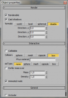
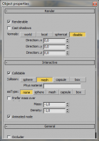
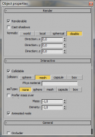
Object Properties Editor
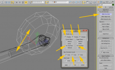
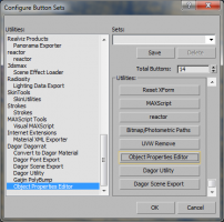
Object properties required for game engine are set with the Dagor “Object Properties Editor” which can be found in 3ds max; Utilities tab. Select Configure Button Sets and add it as a button to utilities panel.
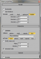
Please set properties for each object that is to be exported. You can set properties for multiple objects at once if they share the same.
Assigning Dagor materials and shaders
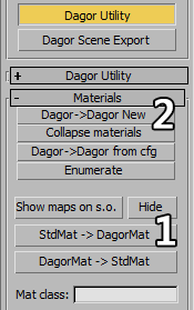
Game materials DagorMat2 with proper shaders have to be assigned to a model prior to export. You can bulk convert all Standard materials assigned to scene geometry to DagorMat2 format using “Dagor Utility”.
- It is located in Utilities tab and can be assigned to a button as well.
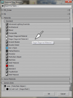
Click on the Standard button inside the material editor.
In the “Dagor Utility” Materials tab press “StdMat -> DagorMat” (1) to convert all assigned standard materials to a previous generation DagorMat material. Then press “Dagor -> Dagor New” (2) to convert DagorMat to DagorMat2. Diffuse texture links are preserved during the conversion. “aces_weapon_fire” shader is used by default in the DagorMat2 material. You can change it later depending on the object purpose or surface type. Also you can switch to DagorMat2 material manually.
And choose Dagor Dagorrat Material 2 material.
Here are examples of common shaders and settings used with Dagor2 materials.
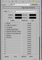
For ID (1) null material, which is used by null-polygons, we have “dynamic_null” shader with no textures assigned.
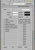
Primary texture ID (2) camo material has “dynamic_masked_chrome_bump” shader. It has a diffuse texture, cube map environment texture and combined normal/specular texture inputs.
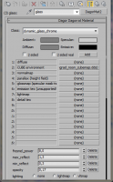
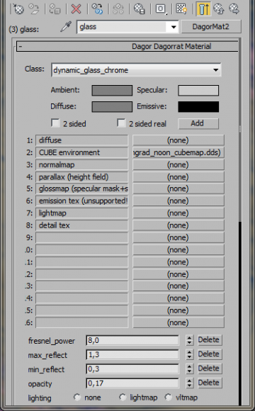
ID (3) glass material uses “dynamic_glass_chrome” shader with only a cube map assigned. It also can have some additional adjustable parameters which are used to control reflections and overall opacity. These parameters can be added by “Add” button under the “Emissive:” color swatch. Usually only opacity is to be added and adjusted. Other settings are kept at their default values. Diffuse color swatch can also be tweaked to colorize glass (to a certain extent).
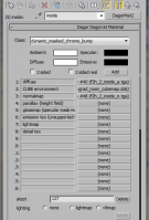
Next typical material is for the “_inside” texture, which utilizes alpha channel. Please note that it has special “atest = 127” parameter which cuts pixels with brightness 127 and below in the alpha channel to make these areas completely transparent. This parameter has to be added to material in order to display alpha channel in the “dynamic_masked_chrome_bump” shader.
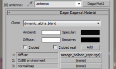
A shader called “dynamic_alpha_blend” is used for objects like antennae or wire bracing. It can show smooth alpha transitions in the 0-255 range by default and typically uses only diffuse texture with an alpha channel as input.
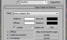
Gunfire material for muzzle flashes uses “aces_weapon_fire” shader and flipbook gunfire texture for input (provided with the sample scene).
Exporting a model
In order to use the model in game it has to be exported from your 3d application into appropriate folder using “Dagor Scene Export” tool (1). This tool is also located in the Utilities tab. The model is exported into *.dag geometry files and *.a2d animation file.
- Naming convention for exported files is following:
- %aircraft_name%.lod#.dag - files for your aircraft lods
- %aircraft_name%_anim.a2d - animation file
- %aircraft_name%_dm.a2d - file for dm parts
- Complete set of files for a chosen aircraft will look similar to this:
- f2h_2.lod00.dag
- f2h_2.lod01.dag
- f2h_2.lod02.dag
- f2h_2.lod03.dag
- f2h_2_anim.a2d
- f2h_2_dm.dag
Objects in the following layers have to be exported to corresponding *.dag files. Only visible objects inside of these layers are exported by default.
*.lod00.dag: GUN LOD0 nodes_gunner pilot prop_side
*.lod01.dag: GUN LOD1 prop_side
*.lod02.dag: GUN LOD2 prop_side
*.lod00.dag: GUN LOD3
*_dm.dag DM
Geometry is exported by pressing “Export DAG” button (2). The file dialog appears and you may save *.dag files where you need them. Object types to be exported are listed under the button and are set correctly by default.
Animation keys are also exported for objects currently visible in the scene so it is a good idea to unhide LOD0 layer and hide everything else before exporting the animation. Animation is exported to *.a2d file in the same folder as your *.dag files. Please make sure animation range checkbox is checked and the range is from 0 to 100 frames. Right below the animation range are thresholds for key optimizations during export. Most notably the position “~pos:” and rotation “~rot:” thresholds are important. Position is measured in your current system units. Rotation is measured in degrees. These values show the amount of change necessary to save out a key if there is one. Default values are used most of the times. If you have undesired animation behaviour in the exported model you may try to lower these values.
Several warning messages may appear during the export process.
- The model has degenerate triangles
- Pieces of geometry have no smoothing groups
- Some parts in the model to be exported are lacking DagorMat2 materials
All of these warnings are written down into the “Export Log” window (4) for each of the object in question. You may want to copy the contents of this window to a text file for convenience.
Degenerate triangles are faces with 0 surface area. It is best practice not to have triangles with surface area less than 1 mm squared. If 3 vertices forming a triangle belong to the same object and share same position this triangle is counted as degenerate. Please weld such vertices with small thresholds. As stated previously all surfaces of the model must have smoothing groups assigned. This will solve the second warning issue. As for missing materials please make sure that you export only geometry mesh objects with DagorMat2 materials assigned to those objects. Helper objects or splines in the scene may result in such a warning. The final scene to export must contain only mesh objects with Dagor2 materials assigned.
Best wishes and Good luck with modeling!
P.s. don't forget to download the guide, below.


